General characteristics of EMC and functional principle of filters
Electrical equipment must function properly in its electromagnetic environment and does not cause unacceptable electromagnetic disturbances to any equipment in its environment. This ability is called electromagnetic compatibility. We classify electromagnetic interference into conducted and radiated interference. Conducted interference includes both symmetric and asymmetric interference (also known as differential mode interference and common mode interference). Symmetrical interference flows between the phase line and the neutral line, while asymmetric interference flows between the phase line and the neutral line to the ground line. The causes of these disturbances include switching operations in network switches, frequency converters, processors, electronics or electrical equipment, motor control, and so on.
The use of X capacitors reduces symmetrical interference. In terms of reducing asymmetric interference, current compensation chokes are used for low interference frequencies and Y capacitors are used for high interference frequencies.
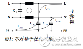
These Y capacitors are connected between the phase/neutral and ground lines and conduct asymmetric interference from the phase/neutral to the ground to create a leakage current (see Figure 1). The larger the capacitance, the better the attenuation effect and the higher the leakage current.
Current limit value that guarantees safe operation of the equipment
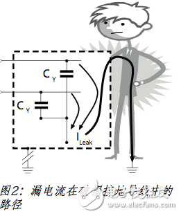
The parasitic coupling capacitance of the device or device and the long power line can cause leakage current to the filter. They will cause the total amount of leakage current to flow through the ground line, posing a safety risk. The higher the electrical impedance of the ground wire, the greater the safety risk the user faces. If a person touches a device with a broken ground wire, leakage current will flow through the body to the ground (see Figure 2).
On the other hand, because the leakage current is too high, any residual current circuit breaker connected to the building network will affect the reliable operation of the equipment. These residual current circuit breakers detect the current flowing into the ground line. Once the current exceeds a certain current limit value, the power supply voltage is disconnected. Therefore, the leakage current limit value enables the device to operate reliably and ensures that no damage will occur even when the ground wire is broken.
Requirements for product developers
Equipment and device manufacturers must ensure that their products meet the requirements for leakage current and electromagnetic compatibility. However, their purpose is to conflict with each other. Normally, these two basic conditions can be met without any special measures. However, it is important that we understand that we are involved in the voltage field. If the filtering effect is good, high leakage current will be generated automatically.
Problems with filter leakage current specifications
Another filter manufacturer will explain the leakage current in its data sheet. However, the IEC filter standard does not specify how to implement the specification. This has led to a situation where different manufacturers are not obliged to use the same method to measure leakage current. Therefore, the data provided by each manufacturer is not directly comparable. On the other hand, equipment standards such as the office equipment standard IEC 60950, the medical equipment standard 60601-1 or the household equipment standard IEC 60335-1 specify the threshold values ​​and the method to be used to determine the threshold values. As a result, equipment and device manufacturers are faced with the problem of complying with standards for managing their products, and have to try to evaluate each filter manufacturer and reconcile the manufacturer's information about leakage current. A calculation model can be used to determine the leakage current. These models are based on idealized conditions. As a result, capacitance and grid voltage tolerances are taken into account, while parasitic effects are ignored. However, when compared to the relatively high tolerances used in the calculations, the error caused by simplification in the ideal model is negligible. Therefore, the capacitance tolerance of the capacitor is specified to be +/- 20%, and in reality, the relevant experience shows that the capacitance tolerance is actually smaller. After the leakage current is measured, a distinction must be made between the single-phase filter and the three-phase filter.
Leakage current of single-phase filter

For a single-phase filter, assume that the neutral and ground wires are at the same potential. To this end, the filter circuit shown in Figure 3 is simplified and represented by the alternative circuit of Figure 4.
Now the measurement of leakage current can be easier:
The expected maximum leakage current condition is a grid voltage tolerance of +10%, a capacitance tolerance of +20%, and a grid frequency of 60 Hz.
Leakage current of three-phase filter
Assuming the load is symmetrical and balanced, the ideal three-phase filter will not generate leakage current even in the case of maximum asymmetric interference. Figure 5 is a cross-sectional view of the Y capacitor in a three-phase filter.

The load of the filter is always in an unbalanced state:
- Y capacitor tolerance - Power supply network imbalance - Asymmetrical load - Undesirable component configuration causes filter
Asymmetry.
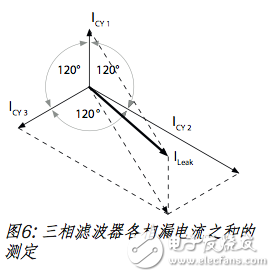
In the three-phase filter, the sum of the phase vectors of the leakage current forms a current that generates a discharge (see Fig. 6).
Leakage current classification
To take into account the various requirements for leakage current, manufacturers classify their products. As a result, filters for standard applications, medical applications, industrial applications, and the like have appeared on the market. Because the patient is in direct contact with the device, it is precisely because of this that the medical field requires more leakage current. In order to maintain the threshold, a small number of Y capacitors are not used or used in most cases. For example, SCHURTER's M5 filter has a maximum leakage current of 5μA (no Y capacitor) or an M80 filter with a maximum leakage current of 80μA.
However, there is no corresponding standard for specifying the level, name, and applicable threshold for leakage current. Nonetheless, this area helps users quickly find the right product for their application.
These Agriculture Drone carries the Granula Spreading System for spreading the 2~6mm dry granula. Such as dry seeds, fertilizer, herbicide etc.
Seed Spreading Drone,Drone Granular Spreader ,Seed Sowing Drone,Seed Spraying Drone
shenzhen GC Electronics Co.,Ltd. , https://www.jmrdrone.com