In most hotels and homes, the lighting system and lighting brightness are adjusted by various types of ordinary switches produced by the switch company. However, with the improvement of people's living standards, it is necessary to produce an infrared remote control transmitter receiver that integrates dimming and switching. Based on this idea, my institute and the School of Information Science and Engineering of Central South University jointly designed a new infrared remote control intelligent home lighting system, which was introduced to the market this year. The following are some important components of this system. The research and design process is described in detail.
1 characteristics of infrared remote control transmitter chip NB9148
NB9148 is a CMOS large-scale integrated circuit used as a general-purpose infrared remote control transmitter. The chip has a wide range of power supply voltage (2.2V-5.5V), low power consumption, few external components, and low price. Therefore, it is here. When designing the lighting system, we chose this chip as the remote control transmitter. Below we use the chip's internal block diagram to analyze its key functions.
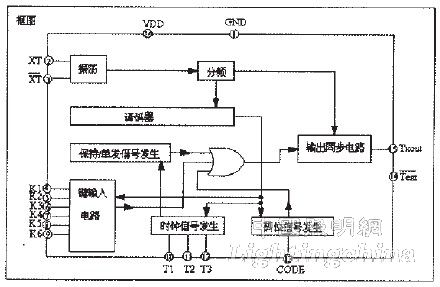
Figure 1 NB9148 internal block diagram
As can be seen from the figure, the oscillator can be formed directly by an external ceramic oscillator or an LC series resonant loop. It is also stipulated that when the oscillation frequency is set to 455 kHz, we can obtain the transmission carrier frequency of the infrared signal is 38 kHz, but if you need to transmit the infrared signal, you must use the K1-K6 input and the T1-T3 timing output connection 6×3. The keyboard matrix, the six keys in the column of T1 can continuously emit multiple sets of infrared control pulses. The keys in the T2 and T3 columns can only be used with one button, and only one infrared control pulse can be transmitted each time. If the number keys on one column are pressed simultaneously, the priority order is K1, K2, K3, K4. , K5, K6. The keys on the same K line have no multi-key function. If the number keys are pressed at the same time, their priorities are T1, T2, and T3.
When a key operation occurs on the keyboard, the infrared command signal corresponding to one cycle of output is a series of 12-bit words. Wherein C1-C3 are user codes, and the remote controllers of different user codes cannot be interchanged. The method of setting the user code is to connect diodes between T1, T2, T3 and CODE to represent C1, C2, and C3 as "1", respectively. If the diode is not connected to one end, it is "0". H, S1 and S2, whether it is a continuous infrared command signal or a single-cycle infrared command signal, when H, S1, S2 values ​​are 100, it means continuous signal, when it is 010 or 001, it means a single group of command signals. , D1-D6 are the transmitted data codes. The data signals corresponding to different buttons are also different, and the picture is the infrared command signal format.
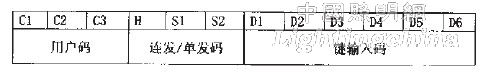
Figure 2 Infrared command signal format block diagram
For example, the data code of key 1 is
It can be seen that the user code is set to 111 and is a continuous signal.
In the infrared signal format of NB9148, the most important thing is to identify the "0" and "1" pulse forms. When the waveform of 0 and 1 is separated, the duty ratio of the positive pulse is 1/4, which means "0". When the duty ratio of the positive pulse is 3/4, it means "1".
Therefore, the key to identifying the infrared signal waveform data is to identify that the high level is a second or the high level is a 3a second pulse in the waveform, and each pulse combination is the data represented by the infrared signal waveform. The application circuit of the infrared remote control transmitter is shown in Figure 3.
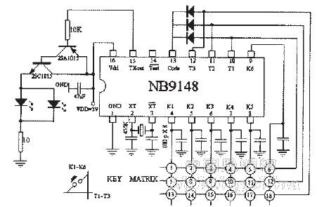
Figure 3 Infrared remote control transmitter schematic
2 Design and research of intelligent lighting system
In the design of the lighting system, we divide it into two components, one is the infrared remote control signal receiving system, and the other is the lighting control system. We will discuss it in detail below.
(1) Design and research of infrared remote control signal receiving system
In the design of the infrared remote control receiving signal device, the traditional method uses the special infrared signal receiving chip NB9148, but this method brings various limitations in the design of our lighting system, for example, the signal output by the chip cannot realize the adjustment of the light. The number of output signal pins is limited, and the number of peripheral circuits leads to a large volume. Therefore, we broke through the tradition and directly replaced the NB9149 and its peripheral circuits with the EM78P156E microcontroller produced by Taiwan Elan. Figure 4 shows the hardware circuit diagram structure using this method:

Figure 4 Infrared signal receiving system circuit diagram
As shown in the figure, the infrared signal emitted by the remote controller is input to the data pin of the EMC78P156 through the integrated infrared signal receiving tube NB0038. The role of NB0038 is to separate the 12-bit infrared signal waveform shown in the figure from its carrier. The data signals are different for different remote control buttons. Therefore, the key function of EM78P156E is to analyze the specific 12-bit data value. In the analysis, we already know that the data “0†is a high level pulse for a second, while the data “1†is a high level for 3a seconds, so in the design of the lighting system, we have taken very effective data. The discriminating method is to set a timer interrupt with a period of 100μS. When a high-jump transition occurs on the infrared data signal input pin of the single-chip microcomputer, the length of the high-level duration is calculated, that is, the timer interrupt occurs during the high-level process. The number of times, if the length of the high level is calculated to be a, the received data pulse is considered to be 0, otherwise it is 1, and finally 12 data combinations are combined to obtain the corresponding key code signal. In the final practice, we reached the correct rate of receiving data above 99%.
(2) Design and research of lighting control system
In the design process of the lighting control system, we used the EM78P156E MCU to control the triac to achieve the purpose of switching and dimming the control lamps. The characteristics of the infrared remote control transmitter chip NB9149 mentioned earlier are mentioned in the keyboard according to the transmitted signal: ?? The button sends a group of infrared signals at a time; after the keyboard is pressed, multiple sets of infrared signals are transmitted until the keyboard release signal ends. For the on or off state of the luminaire, we use the first type of keyboard to transmit signals. The remote control button is used once. The EM78P156E single-chip output control thyristor turns the luminaire from the on state to the off state. Once again, the EM78P156E MCU output controls the thyristor. Turning the luminaire from off state to on state, the software design for controlling the opening and closing of the luminaire is relatively simple. After obtaining the infrared signal, the EM78P156E outputs a level signal through the XOR method. The purpose of the XOR operation is to ensure the current output of the MCU. The level of the current is opposite to the level of the previous output, so that the lamp can be turned on and off.
The adjustment of lighting (dimming) is a difficult point in the design of lighting control systems. So far, most of the systems that the predecessors have done are implemented by hardware methods. This is also the rotation of dimming lamps installed in homes and hotels. The reason for the push button switch, however, the infrared remote control smart home lighting system we designed must use the remote control button to achieve dimming, so the hardware method of the rotary button cannot be used, and the dimming must be implemented by a software method. In order to understand this method, from the essence of dimming, the adjustment of the light can be achieved by changing the voltage on the luminaire. In the intelligent lighting system we designed, the conduction angle of the triac is changed by the EM78P156E microcontroller. Achieve the purpose of changing the voltage on the luminaire.
Familiar with the dimming principle of thyristor, we can know the key to dimming. At the moment when the EM78P156E MCU obtains the trigger pulse from the infrared signal of the remote control, in the intelligent lighting control system, the dimming button uses two buttons, namely brightness. Add button and brightness reduction button, these two buttons belong to the second type of button of the remote control, that is, the keyboard emits successive sets of infrared signals after pressing, until the keyboard release signal ends. Let's take the brightness reduction button as an example to describe the software dimming method; the software dimming program is divided into two parts, the timer interrupt subroutine and the main program, the timer interrupt program is specified every 100μS, and the timer interrupt subroutine contains one. The interrupt variable factor is used to calculate the number of times the timer interrupt occurs. The variable factor is cleared to 0 at each time when the 0HZ AC voltage U(in) is detected. It can be seen that the maximum value of the variable factor is 100, that is, it is detected. The half cycle length of the adjacent 50HZ AC voltage is 10ms. It can be seen that the larger the interrupt variable factor is, the farther the moment is from the positive zero point of the AC voltage. The main program is used to calculate the number of groups of infrared signals that are continuously transmitted. When the number of groups is larger, the longer the button is pressed, the longer the button is pressed. When the number of groups is equal to 100, the group value is kept constant, and the brightness is considered to have been reduced to the maximum. weak. The program stipulates that when the number of infrared signal groups acquired when the dimming button is released is equal to the timer interrupt variable factor, the EMC microcontroller outputs a trigger pulse to the triac to turn on the thyristor. It can be seen that as the number of acquired infrared signal groups increases from small to large, the distance from the moment when the trigger pulse is emitted from the positive end of the alternating voltage is also increased from small to large. According to the thyristor dimming principle analyzed above, the voltage output from the thyristor to the lamp can be known. It is also made up of large scales and light from dark to dark, thus achieving the purpose of dimming. So far, we have analyzed the hardware and software design principles of a complete intelligent lighting system. The software design flow chart is given below.
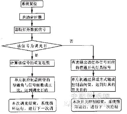
Figure 5 system software design flow chart
3 Conclusion
In the design process of the system, the error rate caused by the infrared data signal reading process and the quality of the software dimming algorithm have obvious influence on the whole system. In the whole design process, we use the method explained above to solve this problem. It is very well solved, its error rate is less than 1%, and the light changes very continuously during dimming.
Edit: Cedar
HuiZhou Superpower Technology Co.,Ltd. , https://www.spchargers.com