Vortex flowmeter under certain flow conditions, part of the fluid kinetic energy will be converted into fluid vibration, the vibration frequency and flow velocity (flow) have a definite proportional relationship, based on this principle of work flowmeter called fluid vibrating flowmeter. At present, there are three types of fluid vibrating flowmeters: vortex flowmeters, precession (vortex precession) flowmeters and jet flowmeters. Vortex flowmeters have the following features:
1 The output is a pulse frequency, whose frequency is proportional to the actual volumetric flow of the fluid being measured and is not affected by the fluid composition, density, pressure, and temperature;
2 wide measurement range, general range up to 10:1 or more;
3 accuracy is in the upper level;
4 no moving parts, high reliability;
5 simple and solid structure, easy installation, low maintenance costs;
6 Wide range of applications for liquids, gases and steam.
working principle
A vortex generating body (baffle) is provided in the fluid, and a regular vortex is alternately generated from both sides of the vortex generating body. This vortex is called a Karman vortex street (see FIG. 1), and the vortices are arranged asymmetrically downstream of the vortex generating body. Arranged. According to the principle of Karman vortex street, there are the following relations:
In the formula, m is the ratio of the arch area on both sides of the vortex generator to the cross-sectional area of ​​the pipe; D is the diameter of the body; d is the width of the vortex generator; f is the frequency of the vortex; U1 is the average of the vortex generator Flow rate; Sr is the Strouhal number; U is the average velocity of the measured medium flow.
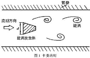
Figure 1 Karman Vortex Street
The volume flow qv within the pipe is:
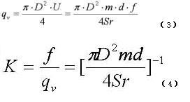
In the formula, K is the meter coefficient of the flowmeter and the unit is the number of pulses/m3.
In addition to the geometric dimensions of the vortex generating body and the pipeline, K is also related to the Strouhal number. The Strouhal number is a dimensionless parameter, which is related to the shape of the vortex generator and the Reynolds number. Figure 2 shows the relationship between the Strouhal number of a cylindrical vortex generator and the Reynolds number of the pipeline. As can be seen from Fig. 2, in the range of ReD=2×10 4 to 7×10 6, Sr can be regarded as a constant, which is the normal operating range of the instrument. When measuring gas flow, the vortex flowmeter's flow calculation formula is:

In the equation, qVn and qV are the volumetric flow rates under standard conditions (0°C or 20°C, 101.325kPa) and operating conditions respectively; Pn and P are the absolute pressures under standard conditions and working conditions respectively; Tn and T are respectively The thermodynamic temperatures under standard conditions and operating conditions; Zn and Z are the gas compression coefficients under standard conditions and conditions, respectively.
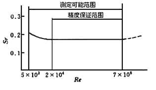
Fig. 2 Curve of Strouhal number and Reynolds number
From equation (4), it can be seen that the pulse frequency signal output by the vortex flowmeter is not affected by changes in fluid properties and composition, that is, the meter factor is only related to the shape and size of the vortex generating body and the pipeline within a certain Reynolds number range. However, in mass balance and energy metering, the mass flow needs to be detected. At this time, the flowmeter should monitor the volume flow and the fluid density at the same time, and the fluid properties and components will have a direct impact on the flow metering.
Vortex flowmeter consists of sensor and converter in two parts, as shown in Figure 3. The sensor includes a vortex generating body (baffle), a detection element, a meter body, and the like; the converter includes a preamplifier, a filter shaping circuit, a DAC, an output interface circuit, a terminal, a bracket, and a protective cover. In recent years, smart flow meters have also installed microprocessors, display communications, and other functional modules in the converter.
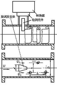
Figure 3 Vortex flowmeter
Application in the field
1 Field application
Vortex flowmeters are widely used for fluids, but are not suitable for low Reynolds number (ReD ≤ 2×10⁴) fluids. Because at the low Reynolds number, the Strouhal number changes with the Reynolds number and the instrument's linearity deteriorates. At the same time, the solid-particle-containing fluid will generate noise when eroded by the vortex generator. The short fibers contained in the vortex generator will change the meter factor if they are wrapped around the vortex generator.
The use of vortex flowmeters in mixed-phase fluids is as follows:
1 can be used for containing dispersed, uniform microbubbles, but the volumetric gas content should be less than 7% to 10% of gas, liquid two-phase flow, if the volume gas content exceeds 2%, the instrument factor should be corrected.
2 It can be used for gas-solid, liquid-solid two-phase flow with dispersed and uniform solid particles with a content of no more than 2%.
3 can be used for mutually insoluble liquid and liquid (such as oil and water) two-component flow and so on.
Pulsating and rotating flows can have a serious effect on vortex flowmeters. If the pulsating frequency coincides with the frequency band of the vortex street, it may cause resonance, destroy normal work and equipment, and cause the vortex signal to generate a "lock-in" phenomenon, at which time the signal will be fixed at a certain frequency. "Locking" is related to the pulsation amplitude, the shape of the vortex generator, and the clogging ratio.
The accuracy of vortex flowmeters is approximately ±0.5%R to ±2%R for liquids and ±1%R to ±2%R for gases, with repeatability generally ranging from 0.2% to 0.5%. Because the vortex flowmeter has a low meter factor and a low frequency resolution, the larger the caliber is, the lower the accuracy is, so the caliber of the meter should not be too large (below DN300).
The range width is a characteristic of vortex flowmeters, but the important point is the flow rate at the lower end of the range. The lower limit of the average liquid velocity is generally 0.5 m/s, and the gas is 4 to 5 m/s. The normal flow of the vortex flowmeter is preferably 1/2 to 2/3 of the normal measurement range.
The greatest advantage of vortex flowmeters is that the meter factor is not affected by the physical properties of the measured medium and can be extended from a typical media to other media. However, due to the wide range of fluid and gas flow rates, the frequency range also varies greatly. In an amplifier circuit that processes vortex signals, the passbands of the filters are different and the circuit parameters are also different. Therefore, the same circuit parameters cannot be used to measure different media.
In addition, the density of gas and liquid is very different, and the intensity of the signal generated when the vortex is separated is proportional to the density, so the difference in signal intensity is also great. The gains and triggering sensitivities of the liquid and gas amplifier circuits are all different. Piezoelectric charge has a large difference, and the parameters of the charge amplifiers are also different. Even if the same gas (or liquid, vapor), with the different pressure, temperature, density, different flow rates used, the signal strength is also different, the circuit parameters also change. Therefore, it is not feasible to change the medium or change the gauge diameter of a vortex flowmeter without hardware or software modification.
2 Installation Precautions The vortex flowmeter is a flowmeter sensitive to the distortion of the flow velocity distribution of the pipeline, swirling flow, and moving flow. Therefore, attention should be paid to the installation conditions of the pipeline on site, and strictly follow the instructions for use.
Vortex flowmeters can be installed indoors or outdoors. If installed in a well, a drowning type sensor should be used to prevent flooding. The sensor can be installed horizontally, vertically or obliquely on the pipe, but to prevent air bubbles and droplets from interfering when measuring liquids and gases, pay attention to the mounting position (see Figure 4).
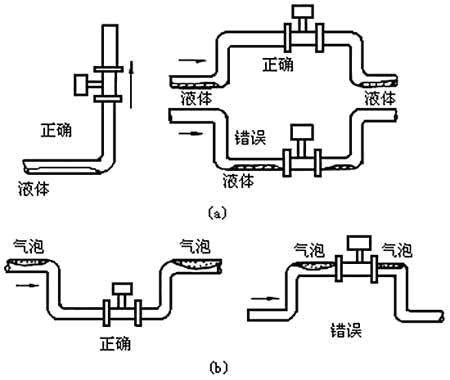
Figure 4 Measurement of Flow Meter Installation with Liquid and Gas-Containing Liquids
Vortex flowmeters must ensure that the upper and downstream straight sections have the necessary length (see Figure 5). 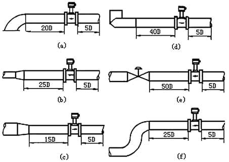
Figure 5 The requirements of the vortex flowmeter for the length of the upper and lower straight pipe sections
In Figure 5, a is a 90° elbow, b is a concentric tube expansion, c is a concentric full-open valve, d is two different 90° elbows, e is a semi-open valve, and f is the same plane Two 90° elbows.
The connection between the sensor and the pipe is shown in Fig. 6. Attention should be paid to the following when connecting with the pipe. 
Figure 6 Connection of sensor and pipe
1 The inner diameter D of the upper and lower piping is the same as the inner diameter D' of the sensor, and the difference satisfies the following conditions: 0.95D≤D'≤1.1D;
2 piping should be concentric with the sensor, coaxial degree should be less than 0.05D';
3 The gasket cannot protrude into the pipe, its inner diameter can be larger than the inner diameter of the sensor by 1~2mm;
4 If there is a need to check and clean the sensor, a bypass pipe should be provided (see Figure 7);
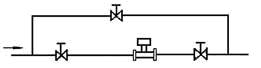
Figure 7 Bypass piping diagram
5 Reducing the effect of vibration on vortex flowmeters should be a concern as a prominent issue in the field installation of vortex flowmeters. First of all, try to avoid the vibration source when choosing the sensor installation place; Secondly, consider using the elastic hose to connect in the small diameter; Thirdly, installing the pipe support is an effective method of vibration reduction.
The electrical installation should pay attention to the use of shielded cables or low-noise cables between the sensor and the converter, the distance should not exceed the provisions of the instructions. When wiring, keep away from strong power cables and try to protect them with a separate metal sleeve. The "one-point grounding" principle should be followed. The grounding resistance should be less than 10Ω. Both the integral type and the separate type should be grounded on the sensor side, and the transducer housing ground point should be “in the same place†as the sensor.
3 common fault phenomena, causes and exclusion methods vortex flowmeter has a variety of detection methods, sensor and measurement circuit is also different, but common vortex flowmeter faults are common.
Conclusion
In many flow meters, the purchase cost of vortex flowmeters is lower than that of mass type, electromagnetic type, volumetric type, etc., and the installation, operation, and maintenance costs are lower than throttling type, volumetric type, turbine type, etc. A more economical, more practical flow meter. The vortex flowmeter has a simple and firm structure and is easy to install and maintain. It is especially suitable for use in industrial sites such as smelters, chemical plants, and oil pipelines.
Vortex flowmeter field application http://
In the rectifier circuit; the use of diodes in series can increase the back pressure withstand value (usually the sum of the back pressure of all diodes, but it is best to use diodes of the same specification).
In the voltage stabilization circuit; the series connection of the diode is equal to the sum of the voltage stabilization value of the diode. The use of diodes in parallel is theoretically the sum of rated currents, but considering that it is impossible to be absolutely symmetrical, they can only be used below 80% of the total.
TVS transient suppressor diodes work in the same way as regulator diodes, but there are structural differences.The biggest difference is that the PN junction area composed of the general regulator diode is very small, it can withstand the reverse current is small.
Transient Voltage Suppressor,Transient Voltage Suppressor Diode,Series diode
Changzhou Changyuan Electronic Co., Ltd. , https://www.cydiode.com