1 Introduction Building a well-developed Intelligent Transportation System (ITS) is the focus of current research. The vehicle navigation and monitoring system is an important part of ITS. It provides the driver with real-time information such as vehicle position, speed, direction and surrounding geographical environment by means of electronic maps to guide the driver to reach the destination quickly, safely and accurately. Based on the project requirements, I and the team members designed and implemented a vehicle navigation and monitoring system based on GPS/GIS and with the aid of a computer network and an existing GSM network communication platform. Thereby, the positioning navigation monitoring and management of the vehicle within the coverage of the GSM network is realized.
2 System overall design 2.1 Design ideas and structure division The system design firstly focuses on the positioning of the vehicle, and then completes its functions of monitoring and navigation. Therefore, it is necessary to combine technologies such as GPS, GIS, GSM and computer communication. The terminal component set on the vehicle in the specific operation will receive the coordinate data from the GPS, and send the information to the control center through the GSM system through the GSM system in combination with the speed and the like, and the control center will display the image on the screen in combination with the background GIS system. At the same time, according to the need to send the control command to the vehicle through the GSM system in SMS mode. In addition, in order to facilitate the user to query the user's basic information, traffic information, vehicle travel information, etc., the control center also needs to transmit relevant information to the WEBGIS server in real time. Therefore, our design of the system is mainly divided into two parts: the vehicle unit and the monitoring center.
2.2 Control Center Design The control center is the core part of our whole system. It needs to receive GPS information from the mobile terminal and graphically reflect it on the GIS platform in combination with the database. At the same time, it should give corresponding feedback to the vehicle based on the monitoring information. To provide navigation of the vehicle. Its functional structure is shown in Figure 1.
This article refers to the address: http://
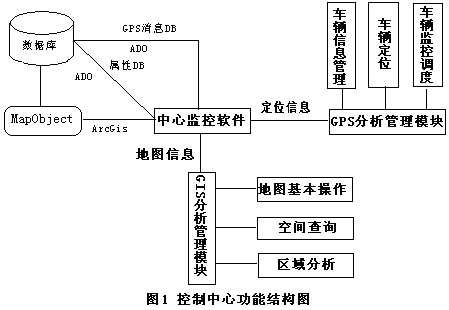
(1) Database design. The requirements of the system for data include geospatial data and non-spatial data. Non-spatial data includes basic attribute data and GPS data. Therefore, three databases are established: geospatial database, attribute database and GPS message database. The geospatial database mainly stores spatial graphic data of GIS. Here, the Chengdu electronic traffic map is the main part, including the spatial location, geometric features and topological relations of the graphic elements of the road traffic network, and other auxiliary features, such as government units. Greenland Plaza, store supermarkets, etc. The attribute database mainly includes basic vehicle information, user information, service information, and the like. The GPS message database is mainly for the management of vehicle location information to facilitate vehicle navigation and path playback. The latter two are structured data, which can be well represented by a general relational database in a table or view manner.
(2) GPS analysis management module. This module mainly deals with the positioning and tracking of the vehicle. The information such as the position and speed sent by the monitored vehicle receiving the mobile terminal is graphically displayed on the map, and detailed records are made in text mode; When playing back, the playback function is designed to include four states: start, pause, resume, and end. It also includes basic vehicle information query processing functions, such as vehicle information inquiry, driver information inquiry, vehicle monitoring inquiry, vehicle scheduling, and the like.
(3) GIS analysis management module. This module mainly integrates secondary development on the basis of MapObject to realize the basic functions of GIS, such as map enlargement, reduction, roaming, query, distance measurement and so on. In addition, according to the needs of the project, the vehicle density analysis function in the road section and the area is realized.
2.3 Mobile Design The mobile terminal is also our vehicle-mounted system. It consists of a GPS receiver module, a DR sensor (Dead Reckoning), a car navigation computer, a communication controller and peripheral devices. The structure is shown in Figure 2. 
The GPS receiver is mainly used to receive satellite signals and solve the positioning information; the DR sensor is used for dead reckoning, which is specially introduced in our system to solve the problem that the GPS cannot be located and the navigation software cannot work; The navigation computer is used for data collection and processing; the communication controller is configured to send data such as the location of the vehicle to the GSM short message center, and receive data such as monitoring instructions sent by the control center through the GSM network. The working principle is as follows: after the GPS receiving module or the DR sensor obtains the data, the data is transmitted to the GSM short message center in the form of short message through the communication controller, and then the data is transmitted to the monitoring center through the local area network or the wide area network, and the vehicle terminal system is interrupted. The method completes the reception of data from the GPS module and the DR sensor, cyclically acquires signals and controls other peripheral devices in the hardware main program.
3 system key technology and implementation 3.1 communication 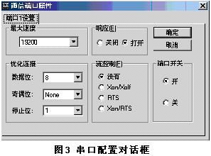
The communication method between the vehicle equipment and the monitoring center is completed by the GSM short message service. The sender sends the data plus the destination address to the short message service center according to the communication protocol, and then sends it to the monitoring center by the short message service center. After receiving the information, the monitoring center also decodes it into the identifiable vehicle latitude and longitude, status and other information by decoding according to the corresponding communication protocol. They communicate with the RS232 full-duplex serial port, which can accept and send data at the same time. Here we use the CserialPortEx serial port class under VC++6.0 to implement serial communication. CserialPortEx is declared as follows
Class CSerialPortEx
{
Public:
BOOL InitPort(CWnd* pPortOwner, UINT portnr = 1, UINT baud = 19200, char parity = 'N', UINT databits = 8, UINT stopsbits = 1, DWORD dwCommEvents = EV_RXCHAR | EV_CTS, UINT nBufferSize = 512);
}
The configuration dialog of the serial port is shown in Figure 3.
3.2 Map Matching Due to the current GPS positioning accuracy of tens of meters, and the US military to limit the use of GPS systems in the military field by other countries, noise interference is artificially added to satellite signals by selecting availability (SA) technology. In addition, due to the complex nature of urban features, when moving in high-density buildings, tunnels, overpasses, etc., it will be affected by its reflection and shadowing, making it impossible to receive GPS signals in some areas and locate blind spots. Therefore, based on GPS positioning and dead reckoning, the positioning point should be matched with the map road, so that the real-time positioning of the vehicle on the map can be realized.
Map matching is to match the GPS track of the vehicle with the vectorized road segment object in the GIS map database to find the actual road currently being used by the vehicle, and then project the positioning point onto the road. According to the driving situation of the vehicle and the need of map matching, the matching positioning is divided into three different states, namely road search, straight travel, and turn. Different treatment methods have been adopted for the characteristics and positioning requirements of each state.
(1) Road search. When the vehicle starts, the road matching may be incorrect, so the road matching should be performed on the starting time in order to establish the correct projection point, which requires a road search first. When conducting road search, we take road connectivity as a consideration, as shown in Figure 4: p0 is the location point matched at the previous moment, p1 is the GPS anchor point at the current moment, and L1, L2, and L3 are within the range to be searched. Three roads. The dotted arrow is the direction in which the vehicle is moving at p0. According to the matching result at the previous moment, it is considered that the vehicle is on the road L1. Since the roads L1 and L2 are in communication, it is impossible for the vehicle to directly enter L3, and it is only possible to search in L1 and L2. 
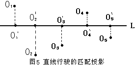
(2) Travel straight. When there is no approach to the intersection of the road, it can always be considered that the vehicle is driving on the road, and all the positioning points can be projected on the road section, as shown in Fig. 5.
(3) Turning. Turning is performed when approaching the intersection. At this point, it can be considered as a new road search, which can be processed by the algorithm of road search.
4 Conclusion Based on GPS/GIS/GSP vehicle real-time monitoring and navigation management system involves GPS technology, communication technology, geographic information science, database, software engineering and other technical fields, the system is more complicated, this article from the overall structure, principle, function, The key technology algorithms and other aspects have made some analysis and research on the vehicle navigation monitoring system. The specific discussion has practical value in the fields of vehicle positioning, navigation and monitoring.
Heat Sink is widely applicable to home appliances, auto parts, medical apparatus,etc.
1. Grade: AL6063
2. Size: T5
3. Standard: DIN 315
4. Certification: ISO9001, ISO14000,IATF16949
|
Product Name
|
Best stainless steel wing nut anchor bolt for construction fastener
|
|
Material
|
Aluminum alloy
|
|
Color
|
Customized Color
|
|
Standard
|
DIN GB ISO JIS BA ANSI
|
|
Grade
|
AL6063
|
|
Brade
|
Rock
|
|
Thread
|
coarse, fine
|
|
Used
|
building industry machinery
|


Heat-Sink,Heat Radiator Sink,Aluminum Heat Radiator,Etruded Heat Sink
Shenzhen Jedver Smart Lighting Co., Ltd. , http://www.jederwell.com