With the development of electronic technology, many intelligent technologies have been widely applied to vehicles. The vehicle rearview mirror system has undergone several generations of technological development as an important safety aid [1]. At present, there are two new technologies in the rearview mirror system: rear view camera and reversing radar. The former image is intuitive and true, but it cannot give an accurate distance; the latter can accurately measure the distance, but it cannot reflect the puddles behind the car, the protruding steel bars, etc., so there is a safe dead angle [2][ 3]. There are several types of radar ranging on vehicles: laser ranging, microwave ranging, and ultrasonic ranging. The former two have a long measuring distance and high measurement accuracy, but the cost is high; the latter has a low cost, but the ranging range is usually small, and the safety is not good when the reversing speed is slightly faster.
This paper proposes a vehicle electronic rearview mirror system based on SOPC technology, which can display the image behind the vehicle in real time, and realizes large-scale ranging of more than 10m by using dual-frequency ultrasonic. At the same time, the system has voice broadcast measurement results and Alarm and other functions.
1 System features
Compared with other electronic reversing systems, this system has the following characteristics: (1) Ultrasonic ranging with two frequencies of 40 kHz and 25 kHz, which not only expands the measurement range but also takes into account the measurement accuracy in small range ranging. (2) The 3.5-inch color LCD screen displays the image of the rear of the vehicle in real time and intuitively, and displays the distance of the obstacle and the speed of the vehicle relative to the obstacle. (3) Voice broadcast ranging results and alarms. The voice chip ISD4002 is used to realize the voice broadcast of the ranging result, and the danger level is automatically evaluated according to the measurement result and the speed of the vehicle relative to the obstacle, and the warning sound is displayed with a prompt sound with a different degree of urgency. (4) System design with SOPC, with great flexibility.
2 hardware circuit design
2.1 system hardware structure
The circuit block diagram of the vehicle electronic rearview mirror system is shown in Figure 1. The whole system can be divided into image acquisition and conversion, image and information display, ultrasonic ranging, voice broadcast and warning, temperature measurement and other parts. The CMOS image sensor OV6620 sends the acquired image data to the FPGA, and the data in RGB888 format is obtained after processing, and sent to the LCD screen through the LCD control circuit for display. The ultrasonic ranging circuit has two channels on the left and right. The distance between the obstacle and the relative speed of the vehicle is measured by two ultrasonic pulses of frequency 40 kHz and 25 kHz. Then the risk assessment is performed and the relevant information is displayed on the LCD screen, and the distance measurement is broadcasted. As a result, the alarm circuit is then controlled to emit a warning tone of a different degree of urgency. 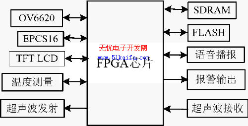
Figure 1 system hardware block diagram
1. 2.2 Design of main function modules
2. 2.2.1 Image acquisition and conversion circuit
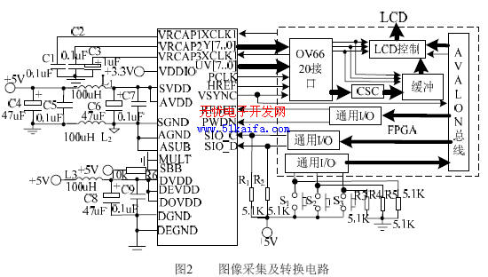
A block diagram of the image acquisition and conversion circuit is shown in Figure 2. The YCrCb4:2:2 format data output by the image sensor OV6620 is converted into YCrCb4:4:4 format data by the deinterleave circuit, and sent to the color space conversion circuit for data format conversion, and then stored in the buffer RAM. The following focuses on the color space conversion circuit.
The image sensor ov6620 outputs data in the YCrCb4:2:2 format, and the lcd screen used in the design requires input of data in the RGB888 format, so a color space conversion circuit is required to perform this conversion. The conversion formula is as shown in equation (1).
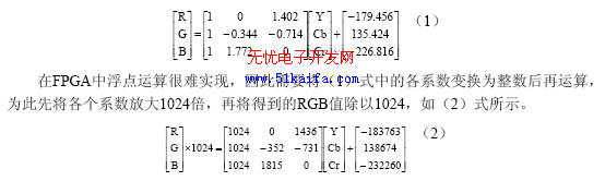
The RGB in the conversion result is an 8-bit unsigned number, ranging from 0 to 255, so the operation result is 0 for the negative number; the operation result is 255 for the 255. This introduces errors, but it does not affect the display of the image. The design of the circuit is completed by VerilogHDL. When the values ​​of YCrCb are 197, 92, and 232, respectively, the GRB output (with delay) is 186, 146, and 255, which is consistent with the calculation according to (1).
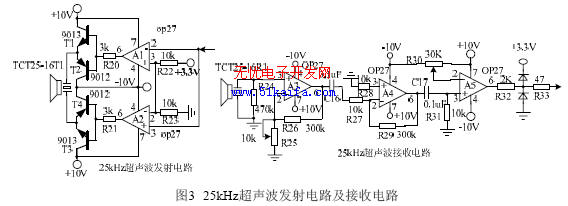
2.2.2 Ultrasonic transmitting and receiving parts If ultrasonic waves of higher frequency are used in ultrasonic ranging, they will be attenuated faster due to larger air absorption, so the measuring distance is shorter. For example, with 40 kHz ultrasound, the range of measurement is generally less than 5 m. Since the absorption of ultrasonic waves by air is proportional to the square of the ultrasonic frequency, reducing the frequency of the ultrasonic waves can increase the ranging range. However, if the frequency is too low, the absolute error of the ranging is larger [4]. In order to balance the range and accuracy, the design uses two ultrasonic rangings of 40 kHz and 25 kHz. The measuring principle is: first output 10 ultrasonic pulses of 40 kHz, and then output 8 ultrasonic pulses of 25 kHz. Since the high frequency ultrasonic waves are emitted first, the echoes reach the CPU first for the same target, so for the close target, the first is high. Frequency ultrasonic detection, the absolute error of measurement is small; for distant targets, since the high-frequency ultrasonic waves are greatly attenuated by air absorption, the echoes only have low-frequency ultrasonic waves. At this time, the absolute error of measurement is slightly larger, but the range of measurement is still large. Acceptable. The received ultrasonic signal is sent to the PIO port of Nios II after being amplified, compared, etc., so that the PIO port is interrupted, the ultrasonic propagation time is obtained by executing the interrupt service program, and the distance of the obstacle is calculated according to the measured environmental thermometer. The relative speed is calculated for two measurements. Only the 25 kHz ultrasonic transmitting and receiving circuit is given here, as shown in Figure 3.
2.2.3 LCD display control circuit
In this design, Samsung's 3.5-inch TFT LCD with resolution of 320 & TImes; 240 (model LTV350QV-F04) is used. The design is divided into two parts: the upper 16 lines are used to display the measured distance, speed and current status. When the information is equal, the lower 224 lines show the image behind the vehicle. In order to improve the display refresh rate and reduce the CPU usage, the LCD display control is implemented by a hardware circuit, and the circuit block diagram is as shown in FIG. The controller uses the line sync signal, field sync signal, pixel clock and other signals output by the OV6620 to generate control signals required to control the LCD screen. In addition, the controller includes a line sync signal counter and a dual port RAM address generator, both of which Cleared when each field signal arrives, then the line counter counts the line sync signal. When the count value is between 16 and 240, the controller sends the image data in the data buffer to the LCD module. When the count value is 0~ The data in the dual port RAM is sequentially read out between 15 to be sent to the LCD screen display. The dual-port RAM in the block diagram is written only for the microcontroller. When the field signal arrives and delays for a period of time (greater than the 16-line data display time of the LCD), Nios II will measure the obstacle distance, speed, etc. that need to be updated. The display data is written into the dual-port RAM; for the LCD controller, the dual-port RAM is read-only, and the data is read at 16 lines from the beginning of each field, so there is no read/write conflict. This design greatly reduces the occupancy of the Nios II processor, allowing the system enough time to complete other tasks.
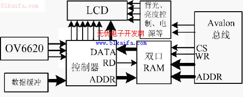
Figure 4 LCD display control circuit block diagram
2.2.4 Voice playback and temperature measurement circuit
The voice playback circuit is mainly composed of a recording and playback circuit ISD4002, a power amplifier circuit LM386 and the like. NiosII realizes the control of ISD4002 through I/O port analog SPI timing, and processes the playback of each segment in ISD4002 in an interrupted manner, thus achieving continuous playback of voice. The temperature measuring circuit is mainly composed of a digital temperature sensor LM75. 3 system software design
The software of this system is more complicated, limited to the space here, only the ultrasonic measurement module is briefly introduced. When performing the ultrasonic measurement module, the number of measurements is first counted. If all channels have completed two measurements (relative speed is calculated from two consecutive measurements), one measurement cycle ends. In one measurement cycle, the time stamp timer T0 is read before each measurement, and the time difference is obtained from the reading result to determine the relative velocity. When transmitting ultrasonic waves, a high frequency wave of 40 kHz is transmitted first, and then a low frequency wave of 25 kHz is transmitted. If the returned ultrasonic signal is not received within 50ms, it means that the ranging range is exceeded and the next channel is measured.
System implementation and testing
Altera's DE2 development board is used as the experimental platform, and the design verification of the system is completed by using two common I/O expansion slots on the platform. The experiment shows that for the planar object, the ultrasonic ranging range of the system is at least 7cm, the maximum measuring range is greater than 10m, and the measuring error is less than ±1cm when the distance is less than 2.5m. The voice prompt is clear and the image displayed on the LCD screen is clear and stable. The system operation is shown in Figure 7. It indicates that the distance from the obstacle (the vehicle in Figure 5) is 6.51m, the speed is 0.65m/s, and the current exposure time is adjusted. The negative speed indicates that it is close. 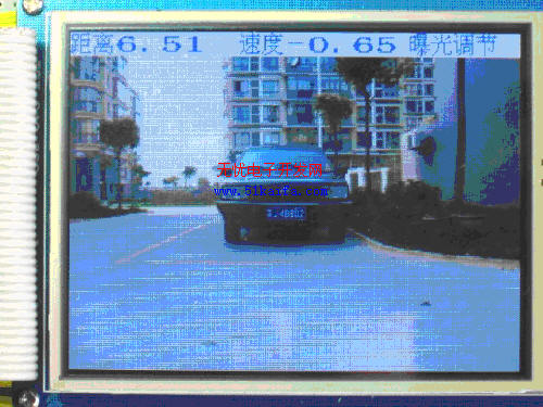
Figure 5 System operation
Conclusion
In this paper, a vehicle electronic rearview mirror system is designed by using SOPC technology. The system uses CMOS image sensor to collect the image behind the vehicle and display it on the LCD screen in real time. At the same time, it realizes wide-range and high-precision ranging with dual-frequency ultrasonic waves. The driver can grasp the situation behind the vehicle in a timely, accurate and comprehensive manner, which greatly improves the safety of the reverse.
The author of this paper innovates: the application of dual-frequency ultrasonic ranging to the reversing radar, expanding the range of general ultrasonic reversing radar; and combining the rear-view imaging and ultrasonic ranging to design a complete vehicle. Electronic rearview mirror system.
For more information on the wonderful information about the rearview mirror, please click on it: http://
Small Flat Switch,Push Buttons,Anti-Vandal Push Button,Vandal Switch
Metal Switch-MU Series Co., Ltd. , http://www.nbswitch.com.cn