Overall speed increase - higher refresh rate and frame change frequency
The LED is driven by the current flowing through, and the pulse width can control the brightness and gray level of the LED. Simply speaking, regardless of the design of the system side, the refresh rate is based on the addressing time (Tacc) and the flow. The current rate of the LED is determined by the current speed; the increase of the frame rate requires faster addressing time in addition to the support of the system, and the addressing time and the transmission clock (DCLK) and the number of addressing are Strong positive correlation.
For example, if there is a full-color outdoor display with a number of addressing of 768, the overall addressing time will be different if different clocks are used.
Working clock is 10Mhz - 768X0.1us = 76.8us
Working clock is 30Mhz- 768X0.033us = 25.6us
The speed at which the current flows through the LED determines the refresh rate of the LED display. For example, if an LED display has an address number of 768, a working clock of 30 Mhz, a grayscale adjustment of 8 bits (bits), and brightness adjustment. It is 2 bits (bits), the interval time between each subfield is 4us; the traditional driver chip shows a pulse width of 250ns, and the pulse width of the SnapDrive driver chip is 50ns, the refresh rate of the two can be significantly different.
A. Traditional driver chip (pulse width is 250ns)
The weights are arranged as 1/64, 1/32, 1/16, 1/8, 1/4, 1/2, 1, 2, 4, 8, 16, 32
Tfr=25.6usx[6+63]+5x4us = 1786.4us
Fr = 559.7Hz
B.SnapDrive driver chip (pulse width is 50ns)
The weights are 1/512, 1/256, 1/128, 1/64, 1/32, 1/16, 1/8, 1/4, 1/2, 1, 2, 4
Tfr=25.6usx[9+7]+8x4us=441.6us
Fr=2264.5Hz
Show grayscale improvement
The OE response time of the conventional general-purpose driver chip currently on the market is about 250 ns. If the above example is used, the highest gray level is 8 bits; that is, R, G, and B each have 256 gray levels. Its color is 256X256X256 = 166777216 about 16 million colors. If you want to increase the gray scale to 14 bits, that is, 16384X16384X16384=4.39 billion colors; the refresh rate between the two will also be significantly different.
A. Traditional driver chip (pulse width is 250ns)
The weights are 1/64, 1/32, 1/16, 1/8, 1/4, 1/2, 1, 2, 4, 8, 16, 32, 64, 128, 256, 512, 1024, 2048
Tfr=25.6usx[6+4095]+5x4us = 105005.6us
Fr = 9.5 Hz
B.SnapDrive driver chip (pulse width is 25ns)
The weights are 1/1024, 1/512, 1/256, 1/128, 1/64, 1/32, 1/16, 1/8, 1/4, 1/2, 1 , 2, 4, 8 , 16, 32, 64, 128
Tfr=25.6usx[10+255]+9x4us=6820us
Fr=146.6Hz
Improvement on Refresh Rate @ 14-bit grayscale + 2-bit Brightness Improvement on Refresh Rate @ 8-bit grayscale + 2-bit Brightness SnapDrive TM Conventional SnapDrive TM Conventional Color 4.39x10 12 4.39x10 12 16.7x10 6 16.7x10 6 Refresh Rate 146.6 Hz 9.5Hz 2264.5Hz 559.7Hz Table 1 shows the comprehensive performance of the traditional driver chip and SnapDriveTM driver chip.
The following is the test conditions and results of the driver chip including SnapDriveTM technology introduced by Taiwan Xunjie Technology. It can be clearly seen from Fig. 1 and Fig. 3 that the output current of the driver chip is still linear output under the minimum OE pulse width, while the conventional driver The chip does not provide a linear output.
Test Conditions:
Vcc=5V, Iout=38.3mA, RL=47Ω, CL=13pF
Reduced distortion rate
For the driver chip with different output current slopes, we use simulation software (HSPICE2007). We get different result distortion rate in terms of distortion rate.
Distortion SnapDrive TM Driver IC 1% Conventional DriverIC 49% Table 2: Distortion Rate Comparison Table
Simulation conditions: traditional driver chip: Ton: 160ns, Tof: 70ns
SnapDriveTM driver chip: Ton: 15ns, Tof: 15ns
Vin : 5V , Iout=20mA , LED equivalent circuit RL: 52Ω, CL: 10pf
OE pulse width is: 250ns
Solve the problem of LED heat and increase the life of LED
As shown in Figure 5, the 50% Dutycycle current output diagram, if the pulse of the current is evenly dispersed in the same time, not only does not affect the output current and the brightness of the LED, it can also avoid LED overheating caused by LED lighting for a long time. And the phenomenon of early decay of life.
Fast response circuit design
The use of a fast-responding driver chip can improve the gray scale and refresh frequency of the LED display; however, the formula according to the inductance effect &D el ta; V = L ?di / dt becomes smaller due to the time t; relatively instantaneous voltage change It is easy to produce a sudden wave. The author has listed several improvements in circuit design for readers' reference:
ΔV : the amount of change in voltage
L: parasitic inductance on the circuit
Di: differential of current
Dt: differential of time
There are a few points that need special attention in circuit design:
1. The PCB is preferably more than 4 layers, and the power supply and the ground are separated by one layer; the shorter the wiring, the better.
2. VLED and VCC add a large voltage regulator to the ground. It is recommended that CP1 and CP2 be 1000~1500uF.
3. VLED and VCC are separated into different power sources.
4. RC circuit can be added to the clock input (Clock) to reduce its peak value and reduce the impact on electromagnetic interference; Rt is recommended
Figure 1: Curve of OE pulse width and output current
Figure 4: Output current distortion rate
Figure 5: Schematic diagram of output current
Figure 6: Driver chip series circuit

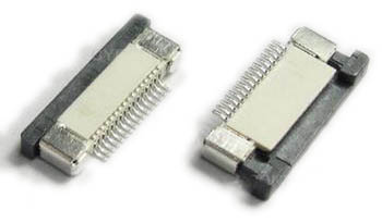
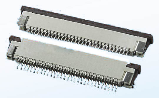
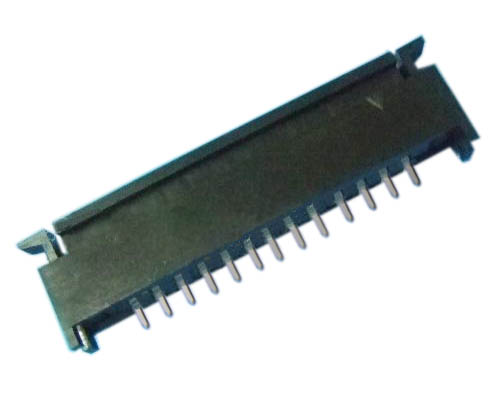
1.ANTENK Flexible Printed Circuit (FPC) and Flexible Flat Cable (FFC) connectors are ZIF (zero insertion force) and LIF (low insertion force) connectors designed to provide a fast, easy, reliable method to make a connection of flexible printed circuits to a PCB. Adam Tech`s special contact design completely preserves conductor integrity by eliminating all wiping action while making connection. Flex circuitry enters the connector and the connector cap is pressed down to capture the flex circuit producing a stable, high pressure connection. Raising the cap releases the pressure for exchange or replacement of circuitry. This series includes single and dual row versions in thru-hole or SMT mounting in vertical or horizontal orientations.
2.Our products are widely used in electronic equipments,such as monitors ,electronic instruments,computer motherboards,program-controlled switchboards,LED,digital cameras,MP4 players,a variety of removable storage disks,cordless telephones,walkie-talkies,mobile phones,digital home appliances and electronic toys,high-speed train,aviation,communication station,Military and so on


Specifications:
Material And Finish:
Insulator: LCP
Lock: PPS
Insert Spring:Phosphor Bronze,
Matte Tin Plated
Solder Platten Area:Phosphor
Bronze,Matte Tin Plated
Voltage:500 V AC(rms)/DC
Current:0.5 A AC(rms)/DC
Contact Resistance:20 mΩ max(initial)
Insulation Resistance:800 MΩ min
Operating Temp:-20°-85°
Fpc Connector,Fpc Cable Connectors,Ffc Cable Connectors,Pitch Fpc Connector
SHENZHEN ANTENK ELECTRONICS CO,LTD , http://www.antenk.com