Given that MEMS processes are derived from lithography microelectronics processes, it is natural to consider IC design tools to create masks for MEMS devices. However, there are fundamental differences between IC design and MEMS design, from layout features, verification or simulation types, to the most important construction issues.
In MEMS design, differences in the magnitude of the object size can lead to a common mistake. The two objects may appear to be connected together on the display, but in reality they may be separated by grid points. If this kind of mistake is not found when it is taken out, it will cause heavy losses. DRCs that can handle curves and polygons can avoid these errors.
When MEMS design contains a large number of curved objects, using IC CAD tools can cause some interesting problems.
Curve objects must be constructed separately and placed on a finer grid than the IC manufacturing process to ensure mechanical "smoothness." In addition, the IC layout tool must now be able to handle polygons with thousands of points (they are generated by discrete curved objects).

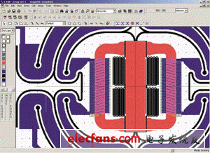
Figure 2: Devices like electromagnetic actuators need
A layout tool that draws precise curves.
Managing such data can slow down the drawing operation. Processing curves and polygons requires appropriate drawing instructions and precise geometric positioning tools to accurately capture midpoints, radii, and angles. In the IC world, pinpointing a center point or a specific distance to a logic gate may not be as important as in MEMS design. For example, for mechanical or inertial purposes, a MEMS designer may need to accurately place a resistor at the center of a curved beam element.
In addition, IC tools may not be able to construct complex curves or objects in a parametric way, forcing the designer to enter detailed x, y coordinates to draw an approximate version of the same device.
Low-cost IC tools usually do not provide algorithm-to-layout generaTIon functionality, so designers may want to use programs such as Matlab or Excel to create x, y coordinate points and then enter CAD tools. Therefore, these objects are "static" and cannot be seamlessly edited.
Unlike mature IC manufacturing, MEMS designers must consider the mechanical physics of processes and devices from a very early stage. For example, in MEMS electromagnetic actuators, three-dimensional (3-D) coils are often difficult to manufacture. In fact, the two-dimensional (2-D) nature of MEMS manufacturing processes often limits the optimal optimization of electromechanical design. Therefore, designers have to use novel layering techniques and fixed process tradeoffs to achieve the right magnetic field.
Closely related to manufacturing are process features and workpieces (arTIfacts). Designers can make some corrections to them directly in the CAD tool. MEMS prepares mask data during the layout design phase. In the L-Edit layout editor, all operations on complex polygons (such as arcs, circles, and similar graphics) can be done in a single step. In some CAD tools, this avoids the time consuming process of copying, pasting, and scaling individual objects one by one.
MEMS designers should pay special attention to large polygons because the resulting polygons tend to have a large number of points when they are polygonized to meet GDSII requirements. Mask companies generally only allow 200 polygons for a single polygon. L-Edit can detect these polygons and automatically break them down into smaller polygons on the GDSII output stream.
For a company, MEMS processes are often proprietary and unique in terms of material selection and hierarchical order. In fact, there are only a few standard processes available. As a result, layout verification is difficult, and those pioneering MEMS companies have little ability to automate layout and schematic comparison (LVS) inspections.
However, custom design rule checking (DRC) tools can be used to discover simple layouts and design errors that suddenly appear in MEMS designs. In the past, the DRC function in low-cost IC tools only handled 45-degree and right-angle objects. Currently, in some of the better tools, DRC has been able to check the minimum spacing between any polygon objects across different layers.
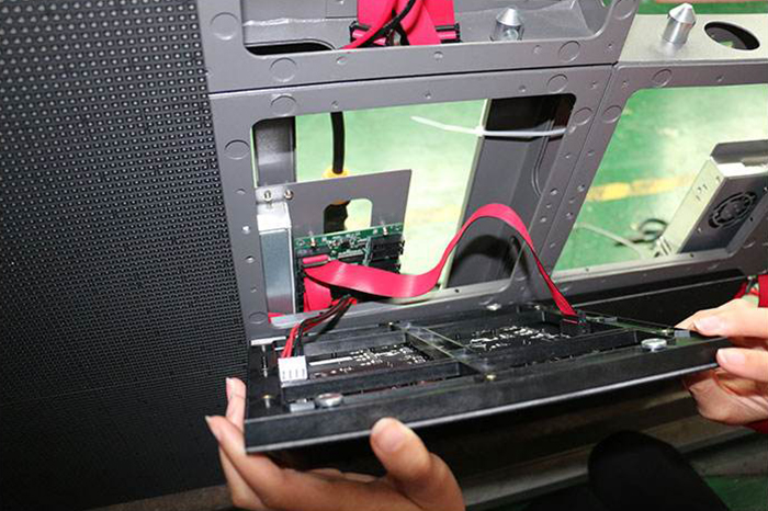
Front access LED Display is easy to maintain and install. with magnet on modules, You can remove and replace any parts from front side, such as LED module, receiver and power supply. the advantage of this design is save space from the screen to wall. can mount directly on the wall, also save time to change the defective parts. both indoor and outdoor, pixel pitch is from P1.2 to P10mm.
Die cast aluminum panel, Linsn and Novastar control system, auto adjusted brightness sensor. with sucking tool will allow you to take out modules easily.
Indoor Rental Front Service LED Display with one single type module, can much reduce the cost for spare parts.Support front service, modules can be taken out without opening the back door,power suppliers are fixed without screws.At the bottom of cabinet, there is special design which can help to protect lamp during installation.
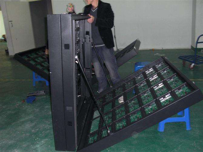
Or we have front open LED sign, which can be flip/open the whole screen at front. but this is only for small size about 2m high. with hydraulic design, it's easy to operate.


Front Service Led Display,Front Service Led Screen,Front Service Indoor Led Display,Waterproof Front Service Led Display
Shenzhen Bako Vision Technology Co., Ltd. , http://www.rentalleddisplays.com