introduction
This article refers to the address: http://
Currently, automakers are gradually replacing automotive lighting systems from incandescent and CCFL (cold cathode fluorescent lamps) to HB (high brightness) LEDs. These HB LEDs are widely used for backlighting of navigation and entertainment device displays as well as for interior and exterior lighting of automobiles, such as daytime running lights, taillights, and the like. HB LEDs are also starting to be used in new applications (eg, head-up displays).
Due to the limitations of the first generation of HB LED drivers, designers are not able to optimize for efficiency, minimum external component count, minimum EMI, and wide-range PWM dimming. The latest multi-string HB LED drivers, such as the MAX16814, solve these technical bottlenecks in an extremely clever way, enabling two-way communication between the switches and linear controllers of these drives. This article describes a design example for a daytime running light or heads up display.
Why choose HB LED?
The increasing popularity of HB LEDs in the automotive sector is easy to understand because they offer automotive designers a number of advantages: HB LEDs are the most environmentally friendly solution compared to other lighting technologies – with outstanding energy efficiency It contains no mercury and has very few harmful substances when it is recycled. In addition, HB LEDs also help to improve the safety of cars, which is due to their fact that they are much higher than the opening and closing speed of incandescent lamps. It is also considered that this factor is widely used in brake lights.
HB LEDs provide designers with more room to play in the “personalized†style of the car. The LED size is small, the light source occupies almost no space on the back of the panel, and the designer can arrange the lamp in any shape, thanks to its small size and directionality of illumination. This small size spotlight is ideal for use as an indicator light.
Finally, HB LEDs have a longer life than other lighting solutions and have a service life of 50,000 hours or more. For this reason, they are ideal for any environment where lighting is maintained for a long time. Daytime running lights are a good application. Case.
HB LED technology also plays an important role in some new applications, such as automotive head-up displays. LEDs have a wide dimming range and are ideal for applications that require adjustment of light levels based on ambient light intensity. It is in these applications that the importance of PWM dimming is reflected.
If you understand why "use" HB LEDs, it is not difficult to understand why they are so popular in today's car design, typical applications include: brake lights, tail lights, front lights (daytime driving, position indication of high-end cars) Lights and high-end cars with high beam and low beam, and internal lighting (RGB LEDs control the color of the lights) add a unique touch to the car. In addition, HB LEDs are becoming mainstream in navigation, entertainment and dashboard backlighting applications (Figure 1).
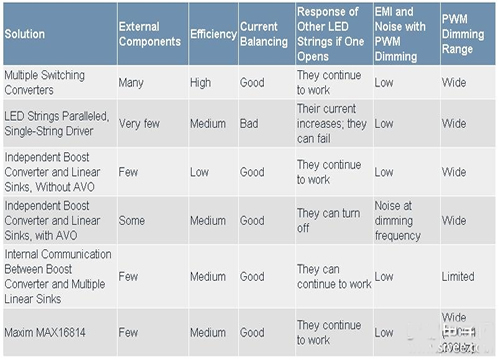
Figure 1. HB LEDs are penetrating into the lighting design of each part of the car, from the front lights to the brake lights and to any part of the lighting between them.
HB LED design challenges
Of course, integrating HB LEDs into automotive applications also presents challenges, such as keeping costs as low as possible. As far as the components themselves are concerned, the price of LED lamps is usually higher than other lighting solutions (eg incandescent lamps, halogen lamps, CCFLs). Therefore, the system-level cost of the LED solution must be reduced to increase the market potential of the technology. In order to reduce the cost of the solution, it is necessary to reduce the number of components of the driver as much as possible, which also contributes to the improvement of system reliability, because each component on the PCB may be a failure point of the system.
Another challenge is efficiency, and energy efficiency is becoming more and more important in cars, especially for hybrid vehicles. Efficiency must be maximized to minimize power consumption (heat generation), automotive components typically operate in high temperature environments, ambient temperatures around the engine can reach +105 ° C, and temperatures in many other applications can reach +85 ° C. LEDs generate a lot of heat (unlike other sources, they don't radiate energy in the IR or UV bands), and their power consumption increases the ambient temperature around them. This requires reducing the power consumption of the LED driver and avoiding overheating of the driver IC or other components in the driver module.
Of course, in the automotive environment, EMI is also an issue. Any lighting subsystem can't interfere with other subsystems in the car. AM radio is usually one of the most sensitive components. Since LEDs require switching or linear drive circuits, these circuits can cause EMI noise (especially switching circuits) or EMI interference problems, and this issue needs to be addressed in the design. The driver circuit also introduces audible noise, such as noise from ceramic capacitors.
Advantages of multiple strings of LEDs
In automotive applications, LEDs are arranged in multiple strings, each string being defined as a set of series LEDs with the same current. LEDs can be conveniently arranged according to the size of the display, and the LEDs can be arranged in multiple strings to help improve fault tolerance. If an LED is open, only the tube in series with the LED will be turned off, not all LEDs. Another reason to use multiple strings of LEDs is to limit the voltage of each string of LEDs and improve system security. For example, after a string of LEDs with a total voltage of 80V is divided into two strings, the voltage becomes 40V, which avoids the high voltage that poses a threat to the human body when it comes into contact with the LED or its connection.
Thus, a single IC capable of driving multiple strings of LEDs has significant advantages. Multi-string architectures typically include: a string of LEDs, a boost converter (the high voltage required to convert the input battery voltage into a string of LEDs), and a multi-route current sink regulator (used to establish the drive current for each string) (Figure 2).
Figure 2. Basic configuration of a multi-string driver that uses a single chip to control the current of multiple strings of LEDs. When the Boost converter and the linear current regulator operate independently, the red marker component can be added to adaptively adjust the voltage.
Compared to a solution with a multiplexer, this solution has fewer components and lower cost (only one inductor and a few bypass capacitors are needed). The advantage of this approach is that the current can be equalized between each string compared to a single string driver that directly drives the parallel LEDs. If multiple strings of LEDs are directly connected in parallel, because some of the LEDs have a high forward voltage, the current cannot be equally divided between each string. In addition, the forward voltage of the LED will decrease with the increase of temperature, and the imbalance of current will cause the heat to run out of control: the LED string with larger current will generate more heat, and the forward conduction voltage will decrease accordingly, thus absorbing more. A large current causes the temperature of the string of LEDs to further increase and cycle. As the current difference increases, one or more strings of high current LEDs may fail. Finally, if the LED strings are simply connected in parallel, since the driver can only control the total current, the failed LED current will increase to other LED strings, causing other LED strings to fail due to overdrive. This situation can be avoided by using the scheme shown in Figure 2.
It is undeniable that the architecture shown in Figure 2 also has certain limitations: it uses MOSFETs to adjust the series current. In order to keep the temperature of these MOSFETs as low as possible, it is necessary to ensure that the voltage across the tube is as low as possible, but sufficient voltage is required to keep the tube in saturation. . Under ideal conditions, the boost output voltage is:
VBOOST = max(VSTRING,I) + VSAT
Where VSTRING, I is the forward conduction total voltage of the first string of LEDs, and VSAT is the VDS when the MOSFET is saturated. An LED driver capable of setting the VBOOST voltage to an ideal value is called AVO (Adaptive Voltage Optimization).
Because most applications require PWM brightness to adjust the LED brightness, the AVO design becomes more complex. They must be turned on and off at a certain duty cycle to turn the linear current sink regulator on and off. However, when all the LED strings are off, what state should the boost converter be in? This is another problem facing the design. There may be multiple answers, each with certain limitations, which will be discussed in detail later.
Traditional multi-string LED driver problem
The traditional multi-string LED driver scheme uses the topology shown in Figure 2, including a boost switching converter and multiple independent working current sink regulators. When these drivers are used to build AVO, some external components are required, which causes a series of problems.
One of the problems is that the external circuit must detect which string of LEDs has the highest forward voltage (or lowest cathode voltage); this can be done with several diodes marked in red in Figure 2. This approach takes up more board space and increases system cost.
This solution has another potential problem in the event of LED failure. If an LED fails to open, the string of cathode voltage will drop to zero. The diode detection circuit will judge that the string has the highest forward voltage and start. Raise VBOOST and try to provide enough drive voltage for this string of LEDs. This will lead to several potential problems. The boosted voltage acts on the current sink MOSFETs of other strings, which may cause all the tubes to fail. Or, the voltage boost will trigger the output overvoltage protection (OVP) of the boost converter if the device has This feature turns off the converter and all LED strings.
The third problem with this architecture is the PWM dimming of the LED. When the LED is off, the diode circuit has no voltage reference point to set VBOOST. One possible solution is to add another diode that is connected to the boost output through a voltage divider circuit, such as the red marker circuit in Figure 2. When the LED is off, the diode turns on and sets VBOOST to the preset voltage. A significant problem with this approach is that the boost converter's output voltage has a high ripple when PWM dimming is performed, and the ripple frequency is the PWM dimming frequency (see Figure 3). Voltage ripple can cause EMI noise. As mentioned above, this is a key issue in automotive design. It also produces audible noise from the output capacitor COUT.
Figure 3a. Waveform when PWM is dimmed by a conventional driver. Using the external circuit shown in Figure 2, VBOOST changes during the on and off of the LED current, and there is a large noise on the power supply.
Figure 3b. In the next-generation driver architecture, the boost converter stops switching during the LED current disconnection. The converter output voltage is held by its output capacitor, which drops slightly due to leakage current.
The advantages of a new generation of multi-string LED drivers
The performance of the new generation of multi-string LED drivers is greatly improved. The boost switching converter and the linear current-sinking regulator can communicate in both directions instead of working independently. Therefore, the new multi-string driver solves the above three problems.
These new drivers detect the voltage of the LED string inside the IC, the drain voltage of each current sinking MOSFET, and the IC uses an internal diode or analog switching circuit to select the lowest string voltage (Figure 4). This solution greatly reduces the number of external components and the cost of the solution.
Figure 4. In a new generation of HB LED driver ICs, the communication between the internal LED sink regulator and the boost converter helps achieve greater efficiency and avoids the problems faced by many traditional drivers.
In addition, the two-way communication function also solves the problem caused by one LED failure or open circuit. In the new design, once an LED fails, VBOOST starts to rise, and when the voltage reaches the OVP threshold, the faulty string can be identified, from the AVO control loop. The string is forbidden or removed, and the other LED strings remain in normal operation. In addition to reducing the brightness of the illumination (rather than turning off the LEDs all at all), there is no other impact on the user.
When adjusting the brightness of the LED by PWM, several factors of the LED driver switching operation need to be considered. The integrated switch and linear regulation loop use a different approach than Figure 2 with lower noise. When the LED is off, the new boost converter can be disabled, as shown in Figure 3b. If the converter stops switching during this time, the power switching MOSFET will remain off and the compensation circuit will be open. At this point, the compensation capacitor maintains its charge, which is the state of the compensation loop. VBOOST is maintained by the output capacitor COUT. Since the LED off capacitor does not discharge, the discharge current of COUT is only leakage current. When the LED is turned back on, the converter restarts the switching operation with minimal ripple. In this scheme, VBOOST is almost constant during PWM dimming, which greatly reduces EMI noise and audible noise generated by the output capacitor.
The only limitation of this approach is that the PWM dimming on-time requires more than a few (eg, three or four) switching cycles so that the boost converter recharges COUT, compensating for leakage current losses during turn-off. This limits the minimum duty cycle that can be achieved.
Next generation drive application
The car's daytime running lights and heads-up displays have the same performance requirements: they remain open during driving, requiring a high reliability/redundancy design to ensure proper operation under all conditions. The use of next-generation multi-string drivers such as the MAX16814 ensures that the running lights and head-up displays are highly reliable while reducing the number of external components. The reduced number of components reduces the probability of failure, helping to increase system reliability and reduce system cost.
This type of application involving personal safety also has similar requirements: it operates over a wide input voltage range and can withstand peak voltages (load throwing) of automotive batteries with typical values ​​up to 40V and has very low EMI.
Fault tolerance is a key consideration, and it is important not to turn off the LEDs even in the event of a fault. The MAX16814 utilizes a multi-string driver architecture to turn off only faulty LED strings in the event of an LED open or short circuit. The other LEDs remain active. In addition, the MAX16814's fault indication output provides an LED failure alarm (Figure 5).
Head-up displays also require a wide (1000:1 or greater) PWM dimming range. The MAX16814 integrates a unique PWM dimming circuit that effectively rejects VBOOST ripple (frequency is dimming frequency), which reduces EMI And audible noise. The MAX16814 solution is similar to the one used in Figure 3b, but is capable of providing an ultra-wide PMW dimming range of 5000:1 at 200 Hz, which is higher than any comparable product, overcoming the above-mentioned minimum on-time limit.
The MAX16814 can drive up to four strings of LEDs with up to 150mA per string and two-way communication between the switch and the linear regulator. The chip greatly reduces the number of external components. In addition, the MAX16814 has complete fault protection and detection functions. Any string of open or shorted LEDs will turn off this string of work and send a fault alarm output to the system. In addition, the IC meets all automotive product design requirements and can withstand 40V load dumps and operates over the -40°C to +125°C temperature range.
Figure 5. This is a complete design example of a car head-up display or a running light drive subsystem that includes all external components and input EMI filters. With the low noise characteristics of the MAX16814, the external EMI filter components can be small.
When designing an HB LED system, there are many factors that need to be compromised, such as component count, efficiency, and reliability. Table 1 compares and summarizes the various LED drive schemes to help designers choose the best solution for their specific application.
Table 1. Summary of HB LED Drive Solutions

The new generation of LED drivers greatly reduces the number of external components. In addition, the two-way communication between the switching circuit and the linear adjustment circuit enables cost-effective solutions, higher efficiency, and improved system performance, including: fault protection and detection. The MAX16814 is a multi-string driver with all of the above advantages, and the PWM dimming range is higher than any similar product on the market.
Glass Encapsulated Thermistor
Glass Encapsulated Ntc Thermistor has the capability of operating in the hostile environment of high temperature and humidity because of glass encapsulated framework. With the properties of small size, fast response, high stability and reliability, this type of thermistor can be used in digital equipment, automatic facility, rechargeable battery, temperature compensation of loops of instrument, integrate circuit, quartz crystal oscillator, thermocouple, air conditioner, heating system, Electric Thermometer, Liquid Level Sensor, automotive, electric table-board and more.
Glass Encapsulated Thermistor,Glass Encapsulated Ntc Thermistor,Liquid Level Sensor,Electric Thermometer
Feyvan Electronics Technology Co., Ltd. , http://www.fv-cable-assembly.com