The cell range we refer to here refers to a radius of 1-3 kilometers. Such a FM transceiver system is more suitable for campus or unit broadcasting. This article will elaborate on the cell FM (stereo) transmitter made by the miniature high-efficiency wireless sound transmission module MEC002A produced by Minshi Technology.
The MEC002A miniature high-efficiency wireless sound transmission module developed by Minshi Technology has the advantages of small size, high RF output power, high sound sensitivity, relatively stable output frequency, etc. The FM transmitter circuit structure composed of it is simple, easy to manufacture and debug Convenient, only need to add a level of RF power amplifier circuit composed of C1971 to realize the FM transmission circuit within three kilometers. The circuit structure is quite simple, so it is more suitable for amateur radio production.
Figure 1 is a three-kilometer mono-frequency FM transmitter circuit composed of MEC002A. It can be seen that its RF circuit actually has only two stages. The first stage is an RF oscillation output circuit composed of MEC002A and related frequency control devices. The other stage It is a Class C RF power amplifier composed of C1971 and related components. The other components are mainly used for power supply, filtering and microphone amplification. Although MEC002A contains a microphone amplifier circuit, for some units, it is necessary to add an external microphone without using the high-sensitivity microphone amplifier circuit in the module. In order to obtain a stable operating frequency, this circuit is provided with multi-stage power supply voltage regulation and filtering Circuit, where U1 (7812) provides a stable 12V voltage for the MEC002A module, and C12-C15 are power supply filter capacitors to make the operating voltage more stable, to ensure that the MEC002A module will not cause frequency drift due to changes in the operating voltage. R3, R7 and L3 are inter-stage decoupling devices, which can effectively overcome the mutual interference caused by the use of the same power supply between all levels. Q1 and its surrounding components form a microphone amplifier circuit. The audio output is coupled to W1 via C5 to control the volume of the microphone. The controlled microphone volume is coupled to the modulation terminal (pin 7) of MEC002A via C8. Perform frequency modulation. Pin 6 of MEC002A is its internal microphone audio amplification output pin. After W2 controls its sound sensitivity, it is coupled from pin C9 to pin 7 and also tunes the frequency of MEC002A's internal high-frequency oscillation circuit. If you want to disable the internal microphone of MEC002A, only Need to suspend its 4 feet, when need to start the internal microphone circuit, it can be achieved by grounding 4 feet. CV1 is the RF output frequency control capacitor of MEC002A. By changing the capacitance, the output frequency of MEC002A can be changed within the range of 68-118MHz. Basically covers the entire campus radio and FM radio frequency band. However, once the output frequency changes, the RF power amplifier at the latter stage must also be adjusted to maximize the RF output power and the farthest transmission distance. Therefore, it is recommended to specify the required operating frequency when purchasing, so that the manufacturer can adjust the gain of the power amplifier circuit at the predetermined frequency point to the maximum. The third pin of MEC002A is its RF output pin. The modulated FM wave is output from this pin through the frequency selection network composed of C16, CV2 and L1 and then sent to the base of the class C amplifier composed of Q2 (C1971), MEC002A Pin 1 is the power supply end, and pin 5 is the power ground. Q2 works in the Class C state, and the bias resistor provides a negative bias for its base, which can make the output efficiency of the circuit higher than that of Class A. The prerequisite is that the front stage must have enough excitation power to work at 12V As for the MEC002A under voltage, its output power is nearly 200mW, which can fully promote the Class C amplifier circuit. U1 provides a stable 15V operating voltage for C1971. L5, L6, CV3, and CV4 form a frequency selection network. By adjusting CV3 and CV4, the output power of Q2 can be effectively transmitted to the transmitting antenna. The working current of the whole machine at 18V operating voltage is about 800mA, RF output power is about 3W. This circuit also provides the mains power supply function. D1-D4 form a full-bridge rectifier circuit, and C30-C33 are filter capacitors, which can reduce the AC ripple caused by the mains. The input AC voltage is controlled at about 18V. The working DC voltage of the whole machine is 18V. When the voltage of 13.5-18V is used, U2 can be eliminated, and the 1-3 pin pads are directly connected with a jumper.
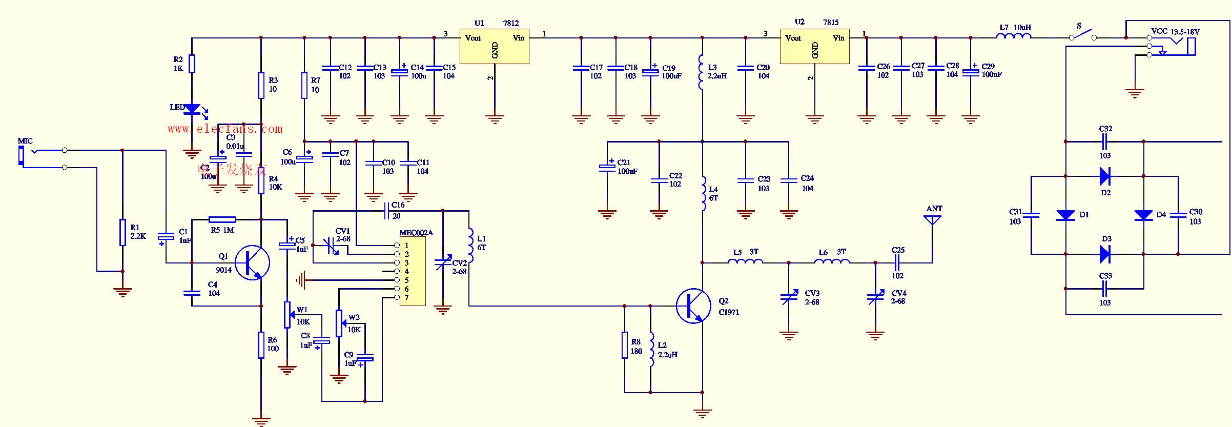
FM stereo transmitter, click on the image above to enlarge the circuit diagram.
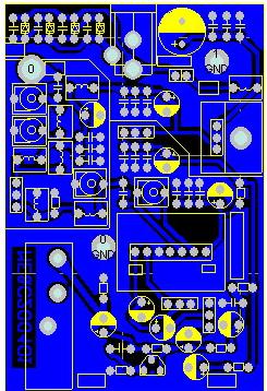
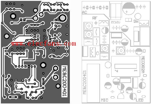
Fig. 2 is the assembly diagram of the whole machine, Fig. 3 is the circuit board diagram of the circuit and the soldering layer, Fig. 4 is the assembly diagram of the component, and Fig. 10 is the assembly diagram of the actual product.
For cell broadcasting, the current mono broadcasting can no longer meet the needs of the majority of music lovers, and more listeners want to receive high-quality FM stereo broadcasting. Figure 6 is based on Figure 1 adds a level of FM stereo coding circuit composed of BA1404, so that the circuit transmission sound quality has been further improved, it can transmit FM stereo signals. BA1404 is a FM stereo modulation transmitter integrated circuit, here we have abandoned its high-frequency oscillation part, and directly used the 19KHz pilot signal output by its 13-pin and the audio signal output by 14-pin to modulate the FM oscillation circuit of MEC002A . The components connected to pins 1 and 18 form an FM pre-emphasis network. With the FM receiver's FM de-emphasis network, the desired frequency response can be effectively obtained and the received sound quality can be optimized. In addition to providing power instructions, the LED also provides a stable operating voltage for the BA1404. The two pads are also reserved for the connection pads of the microphone volume control potentiometer and power switch. The user can modify it according to the schematic diagram, and add the power switch and microphone volume control potentiometer.
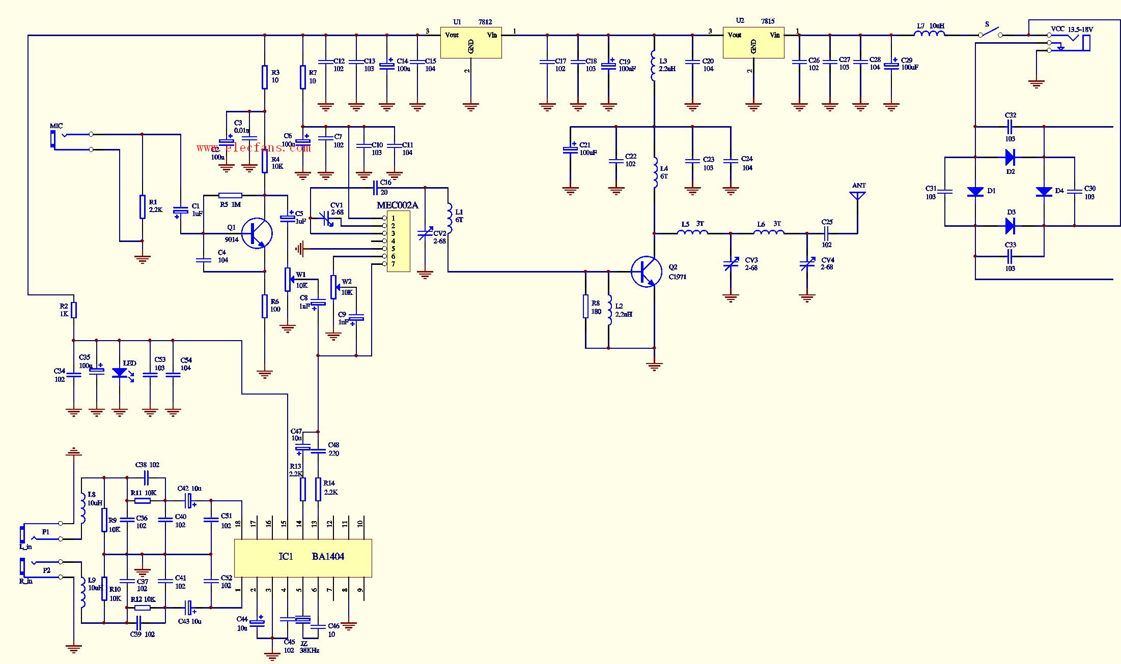
Figure 7 is the assembly diagram of the FM stereo three-kilometer board, Figure 8 is the solder layer circuit board diagram of the circuit, Figure 9 is the component assembly diagram, and Figure 10 is the physical assembly diagram.
Precautions for use: (1) Audio source and antenna: Due to the slightly higher transmission power of the unit, the field strength it generates is sufficient to affect the normal operation of the surrounding electrical appliances with poor shielding. It is recommended to use the above two transmissions during use The board is shielded with a metal box and leads the antenna to the outdoor or a place far away from the sound source. During the actual test, this circuit board uses a whip antenna to directly lock on the circuit board for transmission. When the MP3 player is used as the sound source, the transmitter is close to the transmitter. The MP3 player is not disturbed, but when the Walkman or VCD player is used as the sound source, it is close. The transmitter board will not work properly within three meters, and other audio sources have not been tested; however, the above phenomenon will not occur when using an outdoor antenna for transmission. In addition, the use of a computer as a sound source should also be far away from the transmitter, especially for the stereo transmitter board, it will produce noise. The outdoor antenna is best to use the GP antenna introduced by the Minshi website or the "half wave dipole" antenna made by the horn antenna. The 50-ohm coaxial cable is used to transmit the RF signal. Using a 1.5-meter whip antenna will greatly increase the transmission distance compared to the 1-meter whip antenna provided with the original board. (2) Power supply: Due to the large operating current of the launch board, the power supply requirements are high, and the output current of the power supply is required to be not less than 800 mA at 18V. Therefore, a power supply with an output power that is too small will prevent the launch board from working properly. For example, if two 9V stacked batteries are connected in series, the battery will be exhausted in a very short time. When the DC adapter is used for power supply, the output current must be greater than 800 mA. The operating voltage must be selected at 13.5-18V. The test power supply we use is made of TL431 precision voltage reference IC. (3) Regarding the solution of temperature drift: The three-kilometer board will generate a small range of frequency drift with the increase of operating temperature in the first few minutes of startup, and finally stabilized at an operating frequency. . Replace the CV2 and CV4 adjustable capacitors in the circuit with fixed ceramic capacitors (with black-point high-frequency capacitors) with a capacity in the range of 20-68P. (Note: The change in the value of CV2 has an effect on the transmission frequency) Fix the heat sink to the metal chassis, increase the heat dissipation area, so that the heat can be dissipated as soon as possible, and a small fan can be added to the heat sink if possible. There are two suggestions that can effectively overcome the frequency drift caused by the temperature of the three-kilometer board.
Aluminum Printed Circuit Board, Recognized Best Solutions for High Power and High Thermal Conductivity
As for Aluminum PCB , we will elaborate on the following aspects
- What is Aluminum PCB?
- More Detailed Introduction of Aluminium PCB
- Aluminum PCB Structure
- Aluminum PCB Advantages
- Aluminum PCB Applications
- Types of Aluminum PCB
- Aluminum PCB Performance
- Classification of Aluminum PCB
- Manufacturing Difficulties of Aluminum PCB
- Design Guidelines For Aluminum PCB
As a Chinese PCB manufacturer, Jinghongyi PCB has rich experience in manufacturing aluminium PCB Board . It provides customers with high-quality aluminium PCB Manufacturing and one-stop aluminium PCB turnkey assembly services, prompt delivery on time, and competitive prices.
What is Aluminum PCB
Among all metal core PCBs, Aluminum Core PCB is the most common type, also known as IMS (Isolated Metal Substrate). Due to its low cost, non-toxic and environmental protection, higher durability and lightweight characteristics, aluminum clad PCB is widely used, and its main task is to dissipate the heat generated by power components. For example, it is used in high-power LED lighting power supply, power module, automobile power controller, computer CPU motherboard, etc.
According to the different design structure and application scenarios of aluminium PCB, there are mainly Flexible aluminium PCB, mixed aluminium PCB, multi-layer aluminium PCB, through-hole aluminium PCB and so on.
More Detailed Introduction of Aluminium PCB
and increased energy use. Using heat-sinks increases the costs and makes assembly more difficult, and the extra weight and volume can cause problems.Safe and effective heat dissipation is very important in applications where high power components generate a lot of heat. Although forced cooling is a method, the disadvantage of forced cooling is that it produces disturbing noise, vibration and increased energy consumption while refrigerating. The use of additional radiators increases costs and makes assembly more difficult, and additional weight and volume can cause other unnecessary problems.

Using a specific PCB structure is usually a better solution. The commonly used solution is the metal core structure. With this solution, the printed circuit board is composed of aluminum plates bearing track patterns. Thermoelectric insulators are used between the track and the board so that heat can pass through the metal core structure, such as the Metal Core PCB .
While LED lighting is widely used, it is also necessary to eliminate the heat generated by LED lighting. Therefore, the development of LED lighting industry directly leads to the increase of PCB using aluminium core. At the same time, the market demand of LED PCB Board is also growing.
Copper may be used as an alternative.
For high-power LED, most customers use aluminum-based PCB; for low-power LED, standard Fr4 PCB is also available. Our PCB manufacturing specifications and construction of most types of metal-based Printed Circuit Boards.
Aluminum Based PCBs are a unique metal-based copper clad laminate. These types of Printed Circuit Boards have good thermal conductivity, electrical insulation and very solid machining performance.
They are also known as Aluminum Clad, Aluminum base, MCPCB (Metal Clad Printed Circuit Board), IMS (Insulated Metal Substrate), Thermally Conductive PCBs etc. Aluminum PCBs were developed in the 1970s, soon after which they`re applications increased dramatically. The first application was their use in Amplification Hybrid Integrated Circuits. Now they are being used at a large scale due to which it is necessary for us to have an idea of Aluminum PCBs and their importance.
Aluminum PCB Structure

AluminumPCBs are actually quite similar to FR4 PCBs. The basic structure of Aluminum PCBs is four layered. It consists of a layer of copper foil, a dielectric layer, an aluminum base layer and aluminum base membrane.

- Copper Foil Layer: the copper layer used is relatively thicker than normal CCLs ( 1oz-10oz). A thicker layer of copper means a larger current carrying capacity.
- Dielectric Layer: the Dielectric layer is a thermally conductive layer and is around 50μm to 200μm thick. It had a low thermal resistance and it suitable for its application.
- Aluminum Base: The third layer isthe aluminum base which is made up of aluminum substrate. It has a high thermal conductivity.
- Aluminum Base Membrane Layer: Aluminum base membrane is selective. It has a protective role by keeping the aluminum surface safe from scraping and unwanted etching. It is of two types i.e. Lower than 120 degree or around 250 degrees (anti high temperature)
Aluminum PCB Advantages

- Lower manufacturing and use costs: Aluminum is a metal that can be found in a variety of climates, so it is easy to mine and refine. Therefore, the costs of doing so are significantly lower than other metals. In turn, this means that manufacturing products with these metals are less expensive as well.Aluminum is a very common metal raw material, its mining and production are very convenient. Therefore, the cost of doing so is significantly lower than that of other metals. Conversely, this means that products made from these metals are also cheaper.
- More energy-saving and environmentally friendly: Aluminum is non-toxic and recyclable. Because it is easy to assemble, the use of aluminium also helps to save energy. For PCB vendors, the use of this metal helps to maintain the health of our planet.
- Better heat dissipation performance:Efficient heat dissipation is the greatest advantage of aluminium PCB. High temperature can cause serious damage to electronic equipment, so it is wise to use materials that can help heat dissipation. Aluminum can actually transfer heat from important components to minimize its harmful effects on circuit boards.
- Higher strength and durability: Aluminum provides strength and durability to a product that ceramic or fiberglass bases cannot. Aluminum is a sturdy base material that can reduce accidental breakage during manufacturing, handling, and everyday use.
- Lighter weight and better elasticity: Aluminum is widely recognized as a light metal. While increasing the heat dissipation performance of high power components, it also reduces the weight of the product itself, and increases the strength and elasticity. In addition, in the transportation of products, lighter weight also saves the transportation cost of products.
- Higher conductivity: Thermal conductance of dielectic used is 5 to 10 times higher than old epoxy glass.
- More effective and reliable: Thermal transfer is more efficient and reliable than regular PCB.
Aluminum PCB Applications

- Audio device: Input, output amplifier, balanced amplifier, audio amplifier, pre-amplifier,power amplifier.
- Power Supply: Switching regulator, DC / AC converter, SW regulator, etc.
- Communication electronic equipment: High-frequency amplifier, filtering appliances,transmitter circuit
- Office automation equipment: Motor drive, etc.
- Automobile: Electronic regulator, ignition, power supply controller, etc.
- Computer: CPU board, floppy disk drive, power supply devices, etc.
- Power Modules: Inverter, solid state relays, rectifier bridges.
- Lamps and lighting: As the advocated promotion of energy-saving lamps, a variety of colorful energy-saving LED lights are well received by the market, and aluminum pcb used in LED lights also begin large-scale applications.
Types of Aluminum PCB

-
Flexible Aluminum PCB
Firstly, Flexible aluminium PCB is a new flexible dielectric developed in the development of aluminium products. It is also a kind of flexible circuit board. Because of the combination of polyimide resin and ceramic filter, it has high flexibility, thermal efficiency and excellent electrical insulation. When used in aluminium PCB products, the expensive cables and connectors no longer need to be used.
Flexible circuit boards have unparalleled flexibility, so flexible aluminum PCB can be arbitrarily folded, twisted or formed in any other desired form. However, it should be noted that once a specific shape is formed, it can no longer be changed like other conventional flexible circuit boards. Or deform.
-
Hybrid Aluminum PCB
In hybrid aluminum construction, non-thermal material is processed and refined separately before it is applied to the thermal materials with aluminum base.
The most common practice is developing 2 layer or 4 layer structure which comprises of FR4 material.
A non thermal material that is bonded with thermal material and aluminum base provides rigidity and helps in the dissipation of heat.
This non thermal bonding is preferred over using all thermal materials because it features less cost and encompasses efficient thermal conductance over regular FR4 products.
No heat sinks or assembly steps are required for the development of this product.
Through hole components can be easily adjusted using component windows on the aluminum base.
This helps in passing the cables and connectors through substrate. Also the seal created by solder fillet eliminates the need of costly adopters.
-
Multilayer Aluminum PCB
Multilayer Aluminum PCBs are very common in power supply products and come with multiple layers of thermally conductive dielectrics.
These materials are very useful when they are combined with one or more layer of circuitry in which thermally conductive dielectric is buried between the layers with the help of blind vias which also act as a signal or thermal vias.
Single layer construction of these designs is not very effective, however, when they come with more complex designs they provide an ideal solution for many applications involving heat dissipation.
-
Through Hole Aluminum PCB
When it comes to most complex constructions, a single layer of aluminum is back-filled and pre-drilled with before applying lamination, forming a Core of a multilayer constructions.
Thermal bonding materials are then used to laminate the thermal materials on both sides of the aluminum.
Once lamination is done, drilling is applied on the assembly.
In order to maintain proper electrical insulation, the plated through holes created as the result of drilling must pass through aluminum clearances.
Aluminum PCB Performance

- Better heat dissipation and conductivity: Compared with ordinary FR4 PCB, aluminium PCB has excellent heat dissipation performance. For example, Fr4 PCB with a thickness of 1.5mm will have a thermal resistance of 20-22 degrees per watt, while aluminium PCB with a thickness of 1.5mm will have a thermal resistance of 1-2 degrees per watt.
- There is no serious problem of thermal expansion or contraction.: each substance has its own coefficient of thermal expansion. The CTE of aluminum (22ppm/C) and copper(18ppm/C)is quite close. Since aluminum PCBs work well in terms of Thermal dissipation they do not have severe expansion or contraction issues. They work excellently and are durable and reliable.
- Dimensional Stability: aluminum PCBs show dimensional stability and stable size. For example, when they are heated from 30-140 degrees, their size only had a change by 2.5%-3.0%.
- Others: Aluminum PCBs can be used in power device surface mount technology. They are effective for use in circuit design because of their performance in terms of thermal expansion of circuit design. They help to prolong products shelf life and product power density. They are also extremely reliable. They can help to shrink the overall volume of the product and is also a cheaper option. They show electromagnetic shielding and high dielectric strength.
Classification of Aluminum PCB

- Universal Aluminum PCB: the dielectric layer used here is made up of epoxy glass fiber pre-preg.
- High Thermal-Conductive Aluminum PCB: the dielectric layer is made up of epoxy resin. The resin used must have high thermal conductivity.
- High-frequency Aluminum PCB: the dielectric layer is composed of polyolefin or polyimide resin glass fiber pre-preg.
Manufacturing Difficulties of Aluminum PCB
The manufacturing process for nearly all aluminum PCBs is essentially the same. Here we will discuss the major manufacturing processes, the difficulties and their solutions.
- Copper Etching: the copper foil used in Aluminum PCBs is comparatively thicker. If the copper foil is over 3oz however, the etching requires width compensation. If it is not according to the demand of the design, the trace width will be out of tolerance after etching. Therefore the trace width compensation should be designed accurately. The etching factors need to be controlled during manufacturing process.

- Solder Mask Printing: due to the thick copper foil there is a difficulty in solder mask printing of aluminum PCB. This is because if the trace copper is too thick then the image etched will have a large difference between trace surface and base board and solder mask printing will be difficult. Therefore, the two-time solder mask printing is used. The solder mask oil used should be of good quality and in some cases the resin filling is done first and then solder mask.
- Mechanical Manufacturing: the mechanical manufacturing process involves mechanical drilling, molding and v-scoring etc. which Is left on internal via. This tends to reduce electrical strength. Therefore, the electric milling and professional milling cutter should be utilized for low-volume manufacturing of products. The drilling parameters should be adjusted to prevent burr from generating. This will help your mechanical manufacturing.
Key Requirements When Selecting an Aluminum PCB Manufacturer
For the most part, all PCB manufacturing follows the same production process regardless of where they are made. The only true differences in suppliers is the level of automation in their process, the newest technology and equipment, and having specific equipment designed to focus on certain types of end products.
For aluminum PCBs, there are several key items that a PCB manufacturer needs to consider if they are going to be able to effectively produce aluminum PCBs in any quantity, including:
- Dedicated Imaging Equipment
Many of our aluminum backed PCBs go into LED applications that are much longer than the standard 18" x 24" or 20" x 24" production panels used in traditional PCB manufacturing. To be able to accurately register and economically produce these parts, a manufacturer must have either a custom piece of 60" wide UV light imaging equipment or a setup capable of screen printing (at one time) an image and then UV curing through an oven.
The old manufacturing process of screen printing half the image and then trying to hand register the first image while screen print the second half is much less effective.
- Specialized Scoring Equipment
The more common equipment that can V score through traditional FR-4 materials is not suited to manage aluminum PCBs. To get the lowest cost possible, we need to get the best yield possible, which means we need to be able to place these parts as close as possible to each other on the production panel. Without V scoring, you must mechanically rout the parts out, which could result in up to 20% loss of your yield, subsequently increasing cost.
Our engineering team has many years of experience helping our customers design arrays that are the most cost effective for them to depanelize.
- Greater Than 40-ton Punch Presses
For aluminum PCBs that are round or have unique features – (slots, large holes, cutouts, etc.) – you will want a manufacturer that can punch out these features. Trying to mechanically rout aluminum PCBs is a very costly way to get these features done in a production environment.
- In-Line Hi-Pot Test
A unique requirement of aluminum PCB is that customers want to know that the product they are getting has passed a hi-pot test. While most PCB manufacturers can do this, it is usually a separate process in a lab that is not located in electrical testing. Epec`s electrical test set up includes a hi-pot test, which dramatically reduces cost for the customer.
The following table presents some of our Aluminum Core materials:

Check our Aluminum core PCB manufacturing capabilities in the following table:

Design Guidelines For Aluminum PCB

The task of aluminum core circuit board is to dissipate the heat generated by power components. Therefore, we recommend installing pure power components in this part of the circuit. The control unit shall be installed on a separate standard PCB.
Drilling distances and diameters
In case of double-sided aluminium-core circuits, the aluminium core must be insulated against throughplating. This is done using an excess of resin when press-moulding the aluminium core with prepregs and copper or by plugging. To this end, the aluminium core must be pre-drilled.
The smallest drilling diameter in the aluminium core is 1,0 mm, the smallest final diameter in the PCB is 0,3 mm. So that the drills are not damaged in these close-set drill holes, a minimum spacing of 1,2 mm is required. This is generally the knock-out criteria for a densely-packed control unit.
Variants of aluminium core circuits
-
Single-sided PCBs on aluminium carriers
Normally, this variant only has drill holes for fastenings.
-
Multilayer PCBs with aluminium core
Copper foils are laminated onto both sides of an aluminium core using prepreg. The PCB can be through-plated. This means that it is also possible to produce multilayers with a 0,5 mm aluminium core.
-
PCBs on metal heat-conducting sheets
Completed PCBs are press-moulded to an aluminium carrier using a prepreg. Benefit: Multilayers can also be used (only single-sided SMD). Partial aluminium carriers are possible. Disadvantage: Poor heat dissipation, as the heat has to be dissipated through the entire PCB.
-
Aluminium-flex
One further possibility is a rigid- Flex PCB structure, where the aluminium carrier works as the rigid area of the PCB. This means that it is also possible, for example, to connect a control unit as a plug connector over the exposed flex area.
Basics of Heat Transfer
At a basic level, a discussion about heat transfer includes two topics: temperature and heat flow. Temperature represents the level of thermal energy that`s available, while heat flow represents thermal energy movement from one place to another.
Microscopically, thermal energy is directly related to a molecule`s kinetic energy. The greater the temperature of a material, the greater the thermal agitation of its molecules. It`s normal for areas that contain a lot of kinetic energy to pass it along to areas with less kinetic energy.
There are some material properties that effectively modulate heat that`s transferred between two areas at different temperatures. These include thermal conductivities, material densities, fluid velocities and fluid viscosities. Together, these properties make resolving many heat transfer problems pretty complicated.
The Mechanisms of Heat Transfer
Heat transfer mechanisms can be grouped into three broad categories:
- Conduction. Areas that have more molecular kinetic energy will send their thermal energy to areas that have less molecular energy. This occurs through a direct collision of molecules, known as conduction. In metals, some of the energy transported from one area to another is also carried by conduction-band electrons.
- Convection. When heat is generated in an electronic device, it`s transported via conduction to an are where it is then transferred to a fluid. That process is convection, and the fluid can take the form of a gas such as air or conventional water.
- Radiation. All materials give off thermal energy in amounts that are determined by temperature. When the temperatures are uniform, the radiation flux is in in equilibrium between objects, and there is no exchange of thermal energy. This balance changes when temperatures vary and thermal energy is transported from areas of higher temperatures to those of lower temperature.
HELP RESOURCES
Quick Turn Aluminum PCB
Aluminium PCB Board for LED
Aluminium Base Metal Core PCB
Aluminum PCBs vs. Standard PCBs
Using aluminium in Flexible Circuits Board
Things You Need To Know About Aluminum PCBs
Aluminum PCB
Aluminum PCB,Aluminum PCB Led,Aluminum Core PCB,Aluminum Circuit Board
JingHongYi PCB (HK) Co., Limited , https://www.pcbjhy.com