1. Introduction Early warning of fire has become an important guarantee for fighting fires, reducing fire damage, and protecting life and property. It is an indispensable safety technical measure for modern fire protection. Automatic fire alarm and control systems have been widely used in various types of construction and engineering. How to make a plurality of independent systems form a unified fire monitoring network is an urgent problem that we must focus on.
The intelligent fire alarm system designed in this paper adopts CAN bus three-level communication network, with fire as the monitoring object, using computer technology, detection technology and field bus technology, designed, constructed and worked according to the requirements and characteristics of fire prevention. The system can not only detect and automatically alarm the occurrence of fire, but also output the joint fire-fighting signal according to the position of the fire, and start the corresponding fire-fighting facilities to extinguish the fire. Practice has proved that the system has the advantages of intelligence, quick response, high reliability, etc., and can better meet the requirements of fire prevention for intelligent buildings. 2, system composition
2.1 CAN bus field bus CAN is a kind of bus topology used in the production of the lowest level. Currently, it has the only international standard field bus, which can realize a fully distributed multi-machine system with up to 110 nodes. The transmission medium is Twisted pair or fiber. With its strong anti-interference ability, high communication speed, long transmission distance, simple system and high cost performance, CAN bus has occupied a place in the whole market and has been widely used in intelligent areas. It has been recognized as the most One of the promising fieldbuses. Compared with the traditional communication bus RS-485 bus, the CAN bus also has many advantages: it works in a multi-master mode, which improves the reliability and spirituality of the system; the perfect communication protocol can be obtained by the CAN controller chip and its interface chip. Realization, which greatly reduces the development difficulty of the system and shortens the development cycle. At the same time, CAN bus has strong processing power and advantages in system network with large data capacity, so CAN bus is very suitable as the backbone channel of the underlying network of intelligent area. Because of the advantages of CAN bus, this paper uses the three-level communication control system formed by CAN bus.
2.2 Three-level communication control system The structure diagram of the three-level intelligent fire alarm system based on CAN bus is shown in Figure 1. The system consists of a three-level communication control system. The three-level communication control system is: first level: the main control computer receives the alarm information of the central controller through the RS-232 bus; the second level: the central controller receives the alarm information of the regional controller through the CAN bus; : The alarm information of the automatic alarm of the user terminal is transmitted to the area controller through the CAN bus. This three-level network can form different network forms. For this case, for small areas, the system can omit the area controller. It can be seen that the system can achieve optimal performance-price ratio and the widest application coverage for different objects, improve product competitiveness, and expand special convenience.
As can be seen from Figure 1, the system consists of a user-side automatic alarm, a regional controller, a central controller, and a host computer. Its working process is: when the system is running, the user-side automatic alarm mainly completes the collection of the fire signal on site. When the user-side automatic alarm detects the alarm, it is transmitted to the regional controller through the CAN bus, and then transmitted to the central controller of the cell management monitoring center through the regional controller, and sends an alarm signal to the relevant department (management center or household owner). . The main control computer in the system also has the function of accurately displaying the alarm information received by the central controller through the LED, such as the building number, the area, the door number and the fire mode suffered by the alarm, prompting the security personnel to promptly Confirm the police and rush to the scene to ensure the safety of the laboratory property and life. Since the CAN bus is limited by the transmission line distance and the number of nodes, its node tolerance is up to 110. Therefore, for the area of ​​large and medium-sized intelligent cells, a scheme using a three-level control system is proposed, that is, in the central controller and the user terminal. A zone controller is added between the automatic alarms. The various parts of the system are introduced one by one below.
This article refers to the address: http://

3. Hardware design 3.1 Hardware design of user-side automatic alarm The user-side automatic alarm is the design focus of this subject. It is a kind of networking function developed by using wireless communication technology and control technology of single-chip microcomputer with CAN controller. The alarm device, which mainly completes the collection of fire signals on site, is one of the important components of the three-level intelligent fire alarm system based on CAN bus. The block diagram of the user-side automatic alarm is shown in Figure 2. It mainly consists of front-end detectors, codec circuits, automatic dialing circuits and voice alarm circuits.
3.1.1 Front-end detectors Traditional front-end fire detectors use single-parameter fire detectors, which have high false alarm rates and false negatives. The system uses multiple fire detectors. In the alarm system, the fire detection signal is detected by multi-detector/multi-criteria, and the multi-fire detection information detected by the detector is comprehensively judged by the single-chip microcomputer. Multi-signal detection is used to complete the real-time detection task of the fire on the one hand, and greatly reduce the false alarm rate of the detector part and improve the reliability of the whole system. The gas leakage detector in this system adopts LH-83 household gas leakage detector of Shenzhen Haoen Company, and the photoelectric induction smoke detector adopts LH-93 photoelectric induction smoke detector of Shenzhen Haoen Company.
3.1.2 codec circuit
Wireless communication between the user-side automatic alarm itself and the front-end detector does not require additional wiring. It is especially suitable for occasions where the user has been decorated and the wiring is inconvenient. This requires an RF receiving and transmitting circuit. The RF receiving and transmitting circuit in this system adopts a low-power, low-cost, general-purpose codec circuit PT2262/2272 manufactured by a CMOS process manufactured by Pucheng, Taiwan. The main function of the RF receiving and transmitting circuit is that the alarm signal sent by the front-end detector is encoded by the encoding chip PT2262, and then received by the decoding chip PT2272 and sent to the microcontroller.
3.1.3 Automatic dialing circuit and voice alarm circuit
Automatic dialing circuit and voice alarm circuit, its main function is to dial the user's pre-set phone number (such as 119, mobile phone number, office number, etc.) to dial the remote alarm when there is an alarm; The voice circuit transmits the pre-recorded voice signal to the owner through the telephone line to realize the voice prompt communication function.
 
3.2 Hardware design of area controller The area controller is mainly used for information management and control of an area user automatic alarm in a building. When the system is running, it waits for the continuous inquiry of the central controller and performs automatic alarm on the user side. Monitor and upload the alarm data to the central controller to realize communication between the host computer and the user's automatic alarm, and provide an effective method for facilitating management and expansion of the system. The use of zone controllers makes the entire system easier to expand, facilitating system commissioning, maintenance and management. The area controller is used to connect the central controller and the user-side alarm. It solves the problem of scattered and large data points of intelligent community nodes, making it easier for the management center to control every user inside.
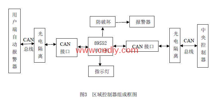
The block diagram of the regional controller is shown in Figure 3. The regional controller selects Intel's 89S52 single-chip microcomputer chip as the control core. On the CAN port side connected to the user-end alarm, the CAN bus transceiver and the optocoupler isolation anti-interference device are installed to solve the problem with the user-side alarm. Handshake problem. On the CAN port side connected to the central control host, a CAN bus transceiver is also installed to solve the problem of signal exchange with the central control host. In addition, the addition of the anti-destruction identification module and the alarm module enables the property monitoring host to detect the human damage to the regional controller line in time and repair it in time.
3.3 Hardware Design of Central Controller The central controller is the bridge and link between the main control computer and the regional controller. It is responsible for the storage and transmission of commands and data between the main control computer and the regional controller. Each room in the intelligent community is equipped with a user-side automatic alarm, so more than one area controller is required. Due to the limitation of communication distance, speed and quality, it is impossible for each area controller to directly execute instructions with the host computer. Communication with the data, so the central controller is used as the intermediate bridge, and the alarm information of the area controller and other data are stored in the central controller in advance, waiting for the host computer to query.
The central controller consists of a structure similar to a zone controller. The difference is that the central controller mainly completes the conversion between the RS-232 signal of the main control computer and the CAN signal of the regional controller. It is the bridge between the main control computer and the regional controller, and is the intermediate storage station of the data.
3. Conclusions In view of the development trend of China's existing intelligent community, this paper proposes a design scheme of three-level intelligent fire alarm system based on CAN bus suitable for large and medium-sized intelligent communities. The intelligent fire alarm system adopts a multi-layer wireless alarm scheme in the front-end fire detection part, which can greatly reduce the false alarm rate and the false negative rate, improve the reliability of the system, and eliminate the need for additional wiring. And its network uses a three-level communication network based on CAN bus to achieve optimal performance and price ratio and the widest application coverage, improve product competitiveness, and expand special convenience. The author's innovation point: the communication network in the fire alarm system uses a three-level communication network based on CAN bus, and uses a multi-layer wireless alarm.
Ethernet Switch,Internet Switches,Ethernet Splitter,Gigabit Managed Ethernet Switch
Chinasky Electronics Co., Ltd. , https://www.chinacctvproducts.com