Abstract: HA7279A is an intelligent keyboard and LED special control chip, which has a serial interface and can simultaneously drive 8 common cathode digital tubes or 64 independent LEDs. The working principle, working sequence and control instructions of the chip are detailed in this article, the actual interface circuit and design program of HD7279A and CPU are given, and some points for attention in practical application are pointed out.
1 Main features
HD7279A is a smart display driver chip with serial interface, which can drive 8-bit common cathode digital tubes (or 64 independent LEDs) at the same time. The chip can connect up to 64-key keyboard matrix at the same time. One LED can complete all functions of LED Display and keyboard interface. The serial interface is used between HD7279A and the microprocessor. The interface and peripheral circuits are relatively simple and take up less lines. In addition, it has a higher cost performance. Therefore, in micro controllers, smart meters, control panels and household Electrical appliances and other fields have been increasingly widely used.
The main features of HD7279A are as follows:
â— With serial interface, LED can be driven directly without external components;
â— You can independently control the decoding / non-decoding, blanking and blinking attributes;
â— With (loop) left shift / (loop) right shift instruction;
â— With segment addressing instructions, it can be conveniently used to control independent LED display tubes;
â— The 64-key keyboard controller contains a debounce circuit. 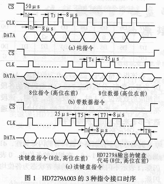
2 Pin description
There are 28 pins in HD7279A. The main functions of each pin are as follows:
RESET: Reset terminal. When the terminal changes from low level to high level and keeps for 25ms, the reset process ends. Usually, the termination is connected to + 5V power supply;
DIG0 ~ DIG7: 8 LED tube bit drive output;
SA ~ SG: LED digital tube output section A ~ G;
DP: decimal point drive output;
RC: external oscillator connection terminal, the typical value of the resistance is 1.5kΩ? The typical value of the capacitor is 15pF.
HD7279A and the microprocessor only need 4 interface lines, of which CS is the chip select signal (active low level). DATA is the serial data terminal. When sending data to HD7279A, DATA is the input terminal; when HD7279A outputs the keyboard code, DATA is the output terminal. CLK is the synchronous clock input terminal for serial data transmission. The rising edge of the clock indicates that the data is valid. KEY is the key signal output terminal, which is high level when no key is pressed; it becomes low level when a key is pressed, and keeps until the key is released.
3 Control commands and interface timing
The control instructions of HD7279A are divided into two categories: pure instructions and instructions with data, which are introduced below.
3.1 Pure instructions
The pure instructions in the HD7279A control instructions are reset (clear) instruction A4H, left shift instruction A1H and right shift instruction A0H. Among them, the reset (clear) instruction A4H is used to clear all the displays, and at the same time to clear all the set characters such as blanking and flashing. After executing this instruction, the chip is in the same state as the system after being powered on. The left shift command A1H can move all the displays from right to left (from the first bit to the eighth bit) by one bit (including the display bit in the blanking state), but it can not afford the blanking and blinking properties set by you effect. The right shift instruction A0H is similar to the left shift instruction, but the movement is from left to right (from the 8th to the 1st position). After the movement, the leftmost bit is empty.
3.2 Instructions with data
The instructions with data include the following 5 types:
| D7 | D6 | D5 | D4 | D3 | D2 | D1 | D0 |
| 1 | 0 | 0 | 0 | 0 | a2 | a1 | a0 |
| D7 | D6 | D5 | D4 | D3 | D2 | D1 | D0 |
| DP | X | X | X | d3 | d2 | d1 | d0 |
(1) Download the data and decode it according to mode 0
The format of this instruction is:
The command consists of two bytes, the first half is the instruction, a2 ~ a0 is the bit address, d0 ~ d3 is the data, when receiving this instruction, HD7279A will be decoded according to the following rules (decoding method 0). which is:
0000: display 0; 1001: display 9
1010: display-; 1111: display blank
(2) Download the data and decode it according to method 1
This instruction is basically the same as the previous instruction, the only difference is the decoding method. The decoding method of this instruction is: the value of d0 ~ d3 corresponds to 0 ~ 9 and A ~ F. The format is as follows:
| D7 | D6 | D5 | D4 | D3 | D2 | D1 | D0 |
| 1 | 1 | 0 | 0 | 1 | a2 | a1 | a0 |
| D7 | D6 | D5 | D4 | D3 | D2 | D1 | D0 |
| DP | X | X | X | d3 | d2 | d1 | d0 |
(3) Download data without decoding
The format of this instruction is as follows:
| D7 | D6 | D5 | D4 | D3 | D2 | D1 | D0 |
| 1 | 0 | 0 | 1 | 0 | a2 | a1 | a0 |
| D7 | D6 | D5 | D4 | D3 | D2 | D1 | D0 |
| DP | A | B | C | D | E | F | G |
In this instruction format, a2, a1, a0 are bit addresses, A ~ G and DP are display data, respectively corresponding to each segment of 7-segment LED digital tube. When the corresponding data bit is 1, the segment lights up, otherwise, the segment does not light up. In fact, this command is relatively flexible, and can be designed to display the characters required by the user by creating a glyph table.
(4) Blink control 88H
This command is used to control the flashing property of each nixie tube, d1 ~ d8 correspond to nixie tube 1 ~ 8 respectively. In the corresponding bits, 0 means flashing and 1 means no flashing. The default state after power on is that no one blinks. The specific instruction format is as follows:
| D7 | D6 | D5 | D4 | D3 | D2 | D1 | D0 |
| 1 | 0 | 0 | 0 | 1 | 0 | 0 | 0 |
| D7 | D6 | D5 | D4 | D3 | D2 | D1 | D0 |
| d8 | d7 | d6 | d5 | d4 | d3 | d2 | d1 |
(5) Reading keyboard data command 15H
The format of this instruction is as follows:
| D7 | D6 | D5 | D4 | D3 | D2 | D1 | D0 |
| 0 | 0 | 0 | 1 | 0 | 1 | 0 | 1 |
| D7 | D6 | D5 | D4 | D3 | D2 | D1 | D0 |
| d7 | d6 | d5 | d4 | d3 | d2 | d1 | d0 |
This command is mainly used to read out the current key code from HD7279A. Different from other instructions, the previous byte of this command is the command transmitted from the microcontroller to HD7279A, and the latter byte d0 ~ d7 is the key code returned by HD7279A. The specific range of this code is 0 ~ 3FH ( When no key is pressed, it is 0xFF).
When HD7279A detects a valid key, the KEY pin changes from high to low and remains until the end of the key. During this period, if the HD 7279A receives the "read keyboard data command", the keyboard code of the current key is output; and if no valid key is pressed when the "read keyboard command" is received, the HD 7279A outputs FFH (11111111B).
3.3 Serial interface timing
In summary, in the instruction structure type of HD7279A, the instruction width of the pure instruction without data is 8BIT, that is, the microprocessor needs to send 8 CLK pulses. The command width with data is 16bit, that is, the microprocessor needs to send 16 CLK pulses. But among them, the command to read keyboard data? The width is also 16BIT? The first 8 BITs are the instructions sent by the microprocessor to HD7279A, and the last 8 BITs are the keyboard codes returned by HD7279A. When this instruction is executed, the DATA terminal of HD7279A becomes the output state at the rising edge of the 9th CLK pulse, and returns to the input state at the falling edge of the 16th pulse, waiting for the next instruction to be received. Figure 1 is the timing diagram of the three command interfaces of HD7229A.
figure 2
4 Application of HD7279A
4.1 Hardware circuit
The typical application circuit of HD7279A is shown in Figure 2. When in use, HD7279A should be connected to a common negative digital tube, and the keyboard and digital tube that are not needed can be disconnected. If the keyboard is not used, the 8 10kΩ resistors and 8 100kΩ pull-down resistors connected to the keyboard in the typical circuit diagram can be omitted. If a keyboard is used, the eight 100kΩ pull-down resistors in the circuit cannot be omitted. Unless the digital tube is not connected, the eight 200Ω resistors connected to the DP and SA ~ SG cannot be omitted.
4.2 Software programming
The keyboard can be monitored through some of the following subroutines, and the key code is read when a key is pressed, so that the display program can be called to display the key value on the LED display. In the interface circuit shown in Figure 2, the external oscillation components of HD7279A can use typical values. The crystal frequency of AT89C51 is 6MHz.
If you connect P1.0 to CS, P1.1 to CLK, P1.2 to DATA, and P1.3 to KEY, then the specific software program code is as follows:
(1) Send one byte subroutine: (the sending number is stored in A)
STFS: MOV R7, # 08H
LP1: RLC A
MOV P1.2, C
SETB P1.1
MOV R6? # 02H
LP2: DJNZ R6, LP2; delay 8μs
CLR P1.1
MV R6, # 02H
LP3: DJNZ R6, LP3; delay 8μs
DJNZ R7, LP1
RET
(2) Subroutine for receiving one byte: (The received character is stored in A)
STJS: MOV R7, # 08H
LP1: SETB P1.1
SETB P1.2
MV R6, # 02H
LP2: DJNZ R6, LP2; delay 8μs
MOV C, P1.2
RLC A
CLR P1.1
MOV R6, # 01H
LP3: DJNZ R6, LP3; delay
DJNZ R7, LP1
RET
(3) Display program (using download data without decoding, the font table is determined by the user according to the need and the hardware connection, the instruction code is 90 ~ 97):
DTR: MOV R5, # 05H
MV R0, # 40H
MV R1, # 95H
LP1: CLR P1.0 (CS = 0)
MV R6, # 0CH
LP2: DJNZ R6, LP2; delay 50μs
MOVA A, R1
ACALL STFS; send instructions
MV R6, # 04H
LP3: DJNZ R6, LP3; delay 25μs
ï¼ï¼¯ï¼ï¼¯ï¼¡, ï¼ R0
AD A, # 0DH
MOVC A, @ A + PC
ACALL STFS; send display code
MV R6, # 02H
LP4: DJNZ R6, LP4; delay 8μs
SETB P1.0; CS = 1
INC R0
DEC R1
DJNZ R5, LP1
RET
TAB DB 7EH, 30H, 6DH, 79H, 33H, 5BH, 5FH, 70H, 7FH, 7BH,
DB 77H, 1FH, 4EH, 3DH, 4FH, 47H, 00H, 67H
(4) Key value reading subroutine: The key value read is saved in unit A and B, and its value is related to the position of the key in the keyboard and hardware connection.
ST: ACALL KEY1
CJNE A, # 0FFH, LP1
CLR 00H
RET
LP1: JB 00H, LP2
SETB 00H
RET
LP2: MOV B, #FFH
RET
KEY1: CLR P1.0; CS = 0
MV R6, # 0CH
LP1: DJNZ R6, LP1; delay 50μs
MOV A? # 15H
ACALL STFS; send instructions
MV R6, # 06H
LP2? DJNZ R6, LP2; delay 25μs
ACALL STJS; read key value
MV B, A
SETB P1.0; CS = 1
RET
COB Light
COB LED par light for theatre, productions, TV studio, stage
Description:
COB200-2in1 is a professional theatre fixture that utilizes a 200W warm-white and cold-white COB LED with a color temperature of 3200k-6000K. Users are able to creat a customized color tempreature via a DMX Controller or set directly on the display menu. It offers a high-power light output with rich hues and smooth color mixing for stage and wall washing. The double bracket makes installing easily and versatile.
Our company have 13 years experience of led display and Stage Lights , our company mainly produce Indoor Rental LED Display, Outdoor Rental LED Display, Transparent LED Display,Indoor Fixed Indoor LED Display, Outdoor Fixed LED Display, Poster LED Display , Dance LED Display ... In additional, we also produce stage lights, such as beam lights Series, moving head lights Series, LED Par Light Series and son on...
COB Light Series,Led Par Light,54 Led Par Light,Par Led Lights
Guangzhou Chengwen Photoelectric Technology co.,ltd , https://www.cwleddisplay.com