1 system composition
This article refers to the address: http://
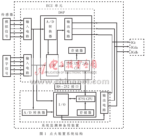
The central processing unit ECU of the system consists of a DSP and a general-purpose microcontroller. DSP is mainly used for signal acquisition, processing, control algorithm implementation, communication with auxiliary unit and PC; single chip is mainly used for system monitoring and standby ignition. The system structure block diagram is shown in Figure 1.

The system uses an integrated ignition assembly. The ignition component is used to complete the functions of closed angle control, constant current control, over voltage protection, parking power failure protection, etc., and can send the ignition signal IGt to the corresponding ignition drive circuit through the cylinder order discrimination signals IGda and IGdb to generate the ignition confirmation signal. IGf.
1.1 main CPU unit
The system main CPU uses DSP TMS320F240. It has the following features: 32-bit central arithmetic logic unit CALU; 16-bit × 16-bit parallel hardware multiplier; built-in 544 words × 16-bit dual-port data / program RAM, 16K words × 16-bit FLASH E2PROM; software waits outside the generator Memory interface module, support hardware wait state; dual 10-bit high speed A/D converter; 28 independently programmable multiplexed I/O pins; phase-locked loop-based clock module; watchdog with real-time interrupt Timer module; serial communication interface; 4-level pipeline operation; 8-level hardware stack; 6 external interrupts; static CMOS technology; 4 low-power modes; maximum frequency is 40MHz; most instruction cycles are single-cycle; The calculation time of the angle is less than 1ms, which is 10 to 100 times faster than that of the general-purpose microprocessor, which greatly improves the real-time performance of the ignition system.
The main CPU unit mainly accomplishes two major tasks: one is to determine the optimal ignition advance angle under the current working conditions, to generate the ignition control signal IGt and the cylinder determination signals Igda and IGdb; the second is to serially communicate with the PC through the RS-232 interface. The main CPU can send various sensor signals, engine speed signals, fault codes, etc. to the PC for simulation and analysis; the PC can also put the binary program code and some important data (such as correction values ​​under different working conditions). Etc.) to the FLASH E 2 PROM unit of the main CPU.
The TMS320F240 expands the four CY7C169-25 and one 8253, and uses the 74F148 to extend the external interrupt source input.
1.2 Monitoring and ignition spare module
The CPU used to monitor and ignite the spare module is 8751. The module monitors and diagnoses each sensor signal, IGf signal, etc., and monitors the main CPU unit. When the main CPU unit fails, the monitoring and ignition standby module immediately takes over the ignition control and abandons the monitoring work.
The 8751 unit expands each piece of 2732, 6264, and 8253. A single A/D conversion was performed using the AD574A and CD4051, and eight external interrupt source inputs were extended with the 74LS148.
1.3 DSP digital controller and PC serial communication
The TMS320F240 SCI module supports digital communication between the CPU and other asynchronous peripherals using the standard NRZ format. The SCI receiver and transmitter are double buffered with independent enable and interrupt bits. The SCI detects the received data, such as discontinuity, parity, timeout, and frame error. The system uses the RS-232 asynchronous serial communication standard bus.
1.4 System Interface Resource Allocation
The I/O interface and interrupt input interface provided by the TMS320F240 DSP digital controller and the 8751 MCU are limited. To avoid resource conflicts, the external input signals are optimally allocated according to Table 1.

2 system software
2.1 ignition advance angle
The ignition advance angle has a great influence on the performance of the engine, and the ECU calculates the ignition advance angle according to the following formula:
Actual ignition advance angle = initial ignition advance angle + basic ignition advance angle + corrected ignition advance angle
The basic ignition advance angle data is stored in the form of a table in the FLASH E 2 PROM of the DSP. In fact, the basic ignition advance angle data is far more than 256. If the engine speed is not at the point where the load is not at the basic ignition advance angle, then multiple linear regression is used to fit:

Where θ is the basic ignition advance angle
n —— engine speed
l - engine load
The coefficients of the linear regression equation generated offline are stored in the ECU. The ECU refers to the basic ignition advance angle data table according to the speed and load information, or refers to the linear regression equation coefficient table to calculate the basic ignition advance angle, and according to other factors that affect the ignition advance angle (cooling water temperature signal, air conditioning switch signal, idle switch signal, etc.) After the necessary correction is made, the ignition control signal IGt is output.
Different models of engines have different ignition advance angles and linear regression equation coefficients. The communication function between the system ECU and the PC provides the convenience of updating these data at any time.
2.2 System Software Module
The software system consists of main program module, control algorithm module, engine speed measurement and processing module, A/D conversion module, G1 and G2 signal interruption module, DSP digital controller and microcomputer communication module, DSP digital controller online program update module, System monitoring module, spare ignition module, FLASH EEROM erase module and so on.
The main program module mainly includes an initialization program, a startup program, an engine condition measurement program, a processing program, a discriminating program, and the like. The initialization of the program includes the initialization of the RAM area, each special function register, I/O, stack, and the like. The main program module determines the operating conditions of the engine based on signals such as engine speed, load, etc., and thereby transfers to the corresponding processing program.
The engine speed measurement and processing module mainly completes the engine working condition determination, check the ignition advance angle data table, etc.; the A/D conversion module processes the conversion of the cooling water temperature and the load signal such as the load sensor; the control algorithm module advances the ignition according to the stored different fuel labels. Data, multiple linear regression coefficients and other tables to determine basic ignition advance data and engine knock control; G1 and G2 signal interrupt subroutine mainly control the generation of IGt, IGda, IGdb signals, detect ignition confirmation signal IGf; DSP digital controller and The communication module of the microcomputer completes the information exchange between the DSP digital controller and the single-chip microcomputer; the system detection and backup module mainly completes the detection of some sensors, the monitoring of the ECU unit, and the ignition control in the standby state; the system monitoring and the standby ignition module pair G1, G2 , Ne, IGf, load, water temperature and other signals are monitored. When a fault occurs, the flag and alarm are set. When the main CPU fails, the module immediately takes over the ignition control in addition to the alarm.
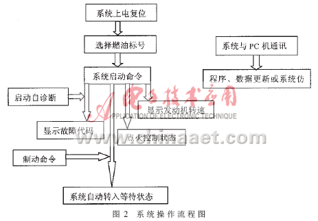
The operation flow chart of the system is shown in Figure 2.

The novelty of this ignition system is that the ECU uses two CPUs, which have self-test and standby functions. The main CPU adopts a DSP that is regarded as a general-purpose chip in the future. This type of chip has the characteristics of fast processing speed, strong computing function, fast input and output speed, high precision, and good reliability, and is suitable for real-time control systems. The system has been commissioned on a car engine and has achieved good engine ignition performance.
references
1 Chen Shuguang. Automotive electrical and electronic equipment. Beijing: Mechanical Industry Press, 1999
2 TMS320C2XX User's Guide.Literature Number: SPRU127B. Texas Instruments, January 1997
3 TMS320C24X DSP Controllers Evaluation Module Technical Reference. Texas Instruments, August 1997
4 Zhuang Jide. Automotive Electronic Control System Engineering. Beijing: Beijing Institute of Technology Press, 1998
5 Zhang Xiongwei, Cao Tieyong. Principles and Development and Application of DSP Chips. Beijing: Publishing House of Electronics Industry, 2000
6 TMS320C1X/C2X/C2XX/C5X Assembly Language Tools User's Guide.Texas Instruments, 1997
7 Wang Wei. Modern Automobile Ignition System——Electronic Ignition and Microcomputer Controlled Ignition. Xi'an: Xi'an Jiaotong University Press, 1997
DC solar gneration system is portable design. Inside has 12V battery and 10A Solar Charger Controller.Three 12V DC output socket can satisified most of your demand. Also bring with a 220V universal socket. When there's emergency and you need to depende on exectronic equioment, our Solar Generation System is the best solution for the need of mobile power. It's very simple and convenient to use.
Dc Ac Inverter,Solar Power System,Dc Solar Generation System,Dc Inverter
Guangzhou City Poojin Electronic Technology Co., Ltd. , http://www.inverter-belttt.com