0 Introduction Traffic accident injuries have increasingly become a worldwide public hazard that threatens human life. Timely detection of traffic accidents and alarms can effectively reduce the casualty rate of traffic accidents.
At this stage, the reduction of traffic accidents is mainly achieved by the use of traffic accident detection devices, which are mainly divided into vehicle detection devices based on magnetic frequency signals, based on spectral signals and based on video signals. Various detection devices use cameras, ultrasound or microwaves to detect traffic events, mainly to deal with macroscopic traffic flow information. This indirect detection technology has the disadvantages of low recognition rate and long delay time, making it difficult for traffic accidents to occur. Get timely and effective assistance.
Since a traffic accident will produce a large collision sound, and the spectrum of the collision sound and other sounds are different. By collecting and analyzing the sound signals around the vehicle to detect the vehicle accident, the accident scene information can be obtained and alarmed in real time, so It is better than the traffic flow analysis method, and can also be relatively improved in the recognition success rate of the accident. Yunlong Zhang proposed a method of analyzing vehicle sounds using wavelet transform to detect vehicle accidents, and got a good recognition effect. Chen Qiang and others from Jilin University used this method to analyze vehicle noise and classify it, which can distinguish the collision information of various vehicles. However, the design of the above algorithms is based on computer data analysis. The actual hardware device is not designed on the basis of this theory, and the accuracy of the algorithm needs to be further improved. Therefore, designing a real-time and high-accuracy vehicle collision sound detection hardware device has high practical value.
In this paper, wavelet analysis and pattern recognition method are used to analyze vehicle noise signals. A DSP-based vehicle collision sound detection device is designed. This device can effectively detect vehicle collision events and realize automatic identification of traffic accidents. Compared with the existing traffic accident detecting device, it has the advantages of high recognition rate and strong real-time performance, and the price is low.
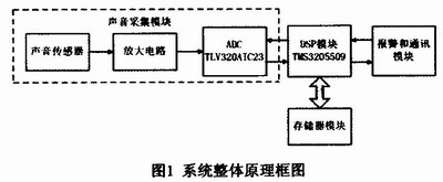
1 Hardware Design The schematic block diagram of the collision detection device we designed is shown in Figure 1. Firstly, various sound signals are collected by the sound sensor. The electrical signal output by the sensor is amplified by the amplification circuit and then transmitted to the analog signal input end of the sound collection chip. The sound collecting chip performs A/D conversion on the analog signal and sends it to the DSP module for further processing. The DSP module processes the collected sound information in real time to determine whether a vehicle collision accident has occurred. The memory module is connected to the DSP module for storing data to be processed and firmware code data, and providing temporary storage space for the DSP module operation. The alarm module and the communication module communicate with the external rescue center. Once the DSP module detects a collision accident, the alarm module sends an alarm message. The main module functions are described below.
This article refers to the address: http://
1.1 Sound collection module The sound collection module uses a capacitive sound sensor with a sampling frequency of 30 Hz to 18 kHz. Since the frequency of the vehicle noise signal generally does not exceed 10 kHz, the sound sensor can perform sampling well. The sound sensor sends the collected analog signal to the amplifier circuit for amplification and then transmits it to the sound collection chip.
The sound collection chip adopts TLV320AIC23B (referred to as AIC23), which is a high-performance stereo audio codec chip of TI company, with 48kHz bandwidth, which can meet the sound signal acquisition requirements including noise signals. The AIC23 performs two-channel stereo A/D conversion on the acquired analog signals, and provides 16-bit, 20-bit, 24-bit, and 32-bit sample data at a sampling rate of 8 kHz to 96 kHz. The system collects external sound signals at a sampling frequency of 32 kHz, collects 32,000 sound data per second, and sets the length of the collected data to 16 bits, so that the analog signal becomes a 16-bit digital signal after A/D conversion. After the analog signal is converted to a digital signal, the AIC23 transmits the data to the DSP module for the DSP module to proceed to the next step.
The system sets the MODE pin of AIC23 to O, the control interface to the working mode of I2C, and the data transmission interface of AIC23 and DSP module to use DSP mode. In this way, the DSP module can control the AIC23 to work together and receive the data collected by the AIC23.
1.2 DSP module
The DSP module is the core of the whole system, which completes the functions of collecting, controlling, storing, processing, and communicating with the outside world. The DSP chip TMS320V-C5509 (referred to as VC5509) produced by TI Company is selected. It is a 16-bit fixed-point DSP with high cost performance. It has multiple high-performance computing units, the system clock is 144MHz, and the command operation speed is up to 1OOMMACS. Provides a rich on-chip expansion interface.
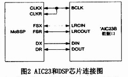
The VC5509 has two multi-channel buffered serial ports (McBSP). McBSP has the same basic functions as a standard serial interface and extends the functionality based on a standard serial interface. The voice acquisition chip AIC23 used in this system is connected by McBSP and DSP, and its connection diagram is shown in Figure 2. CLKX is the transmit clock and CLKR is the receive clock, which are all connected to the system clock BCLK of AIC23. FSX and FSR implement frame synchronization for transmit and receive, corresponding to the LRCIN and LRCOUT pins of AIC23. The data transmission pin DX and the data reception pin DR are respectively connected to the DIN and DOUT of the AIC 23 to perform serial data transmission and reception operations.
The VC5509 also contains six programmable DMA channels. The DMA controller can transfer data between internal memory, external memory and on-chip peripherals without CPU intervention. When the operation is completed, the DMA controller can send an interrupt request signal to the CPU. . The system uses a DMA channel 0 to read in data from the data acquisition module and write to a specific location in the external memory. When the data acquisition is full, the DMA controller will generate an interrupt and control the DSP to execute the data processing program. The use of DMA reduces the number of system interruptions and significantly increases the speed of the system.
For the sound data collected by the sound collection module, the DSP module runs the detection software to analyze it and determine whether there is a collision outside. The DSP module also brings up an IO port to communicate with the alarm and communication module. The alarm and communication module receives the signal from this pin to determine whether a collision has occurred to determine whether to alarm.
1.3 Memory Module VC5509 supports a unified addressing space. The total on-chip memory capacity is 320kB, including 128k×16bit RAM and 32k×16bit ROM, and can be extended to a maximum of 8M×16bit off-chip according to user needs. Memory space. The system uses the HY57V64 chip, which is a SDRAM chip with four 1M×16bit logic arrays. The chip receives and stores the acoustic signal data transmitted by the DSP module, and when the DSP module needs to process the data, the corresponding data is also read from a specific position of the chip.
1.4 Alarm Module The alarm module is equipped with GPS and GSM modules to obtain position and speed information and communicate with the server. The DSP module obtains the speed and acceleration information of the vehicle from the GPS module of the alarm module and adds acoustic signal information for auxiliary calculation. The alarm module obtains real-time vehicle collision information from the DSP module. Once the collision signal is detected, the alarm module alerts the server.
2 software and algorithm design The system software we designed is a program running on the DSP, control system modules work, and complete algorithm calculation. Use TI's CCS integrated development environment to program in C and assembly language.
The software is first initialized to configure the operating parameters of the VC5509 and AIC23. When configuring the phase-locked loop of the VC5509 chip, set the system clock to 144 kHz. When configuring McBSP, open McBSP0 of VC5509 and start it for input and output operations. Configure the DMA0 channel to operate in compatibility mode and stop data transfer on interrupt. Configure the AIC23 to work in DSP mode and use IIC to transfer data. The AIC 23 is enabled to sample the acoustic signal at a 32k sampling rate.
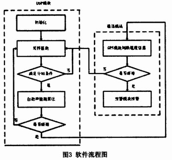
After the initialization is completed, the sampling detection is performed. After the sampling detection, once the collected signal is found to satisfy the framing condition, that is, the collected acoustic signal has a length of 1 second, the automatic acoustic detection algorithm is executed.
The automatic acoustic detection algorithm reads out the data and makes a judgment. If a non-collision event is detected, the sampling detection is continued to wait for the next second data to be processed, and the software is performing an empty loop; when the automatic acoustic detection algorithm detects the collision Event, the information is transmitted to the communication module, and the alarm module alarms after the GPS module confirms the speed and position information. The flow of this software is shown in Figure 3.
The design of the automatic sound detection algorithm in the software flow chart is the core part. The following is a key introduction. Due to the different amplitude-frequency characteristics and phase-frequency characteristics of different acoustic signals, the amplitudes of different acoustic signals in different frequency segments also have some differences. Therefore, the energy change of each frequency component can be utilized to achieve target recognition.
The automatic sound detection algorithm includes four parts: sound signal acquisition and framing, feature extraction, feature dimension reduction, and feature classification. The specific implementation steps are as follows:
(1) Acquisition and framing. The collected signal is divided into one frame every 2s, and there is an overlap of 1s between the frame and the frame. For a chip with a sampling rate of 32k, that is, only 65,536 points of the 2s segment are processed each time, and there are 1/2 repetitions between the two segments in the training phase. This gives a set of data Datai (1 ≤ i ≤ 65535).
(2) Feature extraction. A DWT transform is performed on each frame signal data Datai (1 ≤ i ≤ 65535) to obtain frequency domain information, and then the distribution of energy is calculated based on the obtained frequency domain information as a feature for identifying a traffic accident. The algorithm uses DB1 wavelet, first decomposes each frame signal, then the high frequency coefficient performs two layers of complete decomposition, and the low frequency coefficient performs 10 layers of unidirectional decomposition to obtain 18 sets of data. The characteristic component F=[E1, E2...E18] is calculated, and the calculation formula of En is as follows: ![]() Where N is the length of Cn.
Where N is the length of Cn.
(3) Feature dimension reduction. Dimension reduction is achieved for the semaphore after feature extraction. Based on the extracted feature component F, the algorithm uses the principal component analysis (PCA) anomaly detection algorithm to detect the traffic accident collision sound. The original feature F is transformed ![]() The formula is
The formula is ![]() Where H is the projection matrix obtained by the PCA method.
Where H is the projection matrix obtained by the PCA method.
(4) Feature classification. Collect sound signal samples around the vehicle during normal operation and traffic accidents, and train the classifier to classify the sound during driving. The classifier intends to output two types of classification results: one is the normal operation sound, and the other is the collision sound of a major traffic accident. The discriminating conditions are: 
among them ![]() Projection of the feature components for the training sample set. n indicates
Projection of the feature components for the training sample set. n indicates ![]() The maximum number of deviations from a given interval Ii is allowed, and when n is greater than a certain threshold, it is a collision, and vice versa is not a collision.
The maximum number of deviations from a given interval Ii is allowed, and when n is greater than a certain threshold, it is a collision, and vice versa is not a collision.
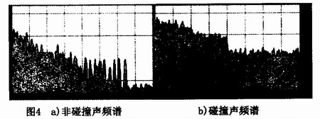
3 Experimental Results and Analysis System The total number of experimental samples used in the experiment was 200, which were divided into two types: collision samples and non-collision samples, each of which was 100 samples. Collision samples are collected from vehicle manufacturers' crash tests, and non-collision samples are collected from everyday common types of sound signals. The collision sample has a length of 10s, which contains the sound of the complete vehicle collision process and is mixed with common noise such as brakes. The non-collision samples are 20s long and are divided into natural environment, music and voice. In the collision sample, 20 training samples are used as algorithms, and the remaining 80 are used to detect the effect of the algorithm. The spectrum of a typical normal sound is shown in Figure 4 a), while the spectrum of a typical crash sound sample is shown in Figure 4 b).
Our collision sound detectors are tested in a simulated environment to restore real-world scenes as much as possible. The low-distortion power amplifier device is used to repeatedly experiment with the collision signals collected in the real scene. And compared with the experimental results in the literature. The overall success rate is the ratio of the total number of samples to the judgment pair and the total number of experimental samples. The experimental results are shown in Table 1.
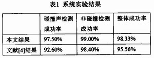
It can be seen from the experimental results that the experimental results are very accurate for both the collision sample and the non-collision sample, which indicates that the algorithm is reasonable in design and can achieve the purpose of collision sound classification under small interference, and the literature mentions Compared to the results, both the collision sample and the non-collision sample have improved accuracy.
4 Conclusion The TMS3205509 chip is used for signal processing and the TLV320AIC23B is used as the vehicle collision alarm device of the acquisition chip, which is small in size and low in cost. This device uses a framing method to perform pattern recognition calculation on the acoustic signal to achieve timely alarm of vehicle collision. The experimental results show that the system has high reliability and short delay, and can issue alarm signals in time. The application of this system can improve the safety factor of motor vehicle occupants, thereby reducing the accident rate of passengers and passengers, and has a good application prospect.
With our expertise in domain, we offer comprehensive range of Monocrystalline Solar Panels. Our products are used amongst the customers across the country for their effectiveness. We offer products to our patrons as per their needs and are easy to install. These products work using solar energy and have high performance.which are made using high quality raw material and advanced technologies. These Polycrystalline Solar Panels are checked for quality on various parameters. These products are highly resistant towards the winds and the hailstones and serves for a longer period of time.
Mono 150W Solar Panel,150W Mono Pv Solar Panel,Mono Solar Panel 150W,150 Watt Mono Solar Panel
Yangzhou Bright Solar Solutions Co., Ltd. , http://www.solarlights.pl