Compared with piston engines, the advantages of turbojet engines (hereinafter referred to as turbojet engines) in terms of thrust-to-weight ratio are undisputed. If it is miniaturized, it will enable small unmanned aerial vehicles to acquire higher speed and load capacity. Therefore, the development of micro turbojet engines has far-reaching significance in the military and civilian fields. At present, the United States, Germany, Denmark and other countries have quite mature micro-jet engine products, which have been successfully applied to aircraft models and drones. But in China, both the engine itself and its control system belong to a newer field [1].
This article refers to the address: http://
In this paper, a general control system of micro turbojet engine based on C8051F021 and MicroStar RTOS is designed for a domestic engine. It is based on the processor and integrates sensors, servos and man-machine interfaces. It is small in size and light in weight. It provides an instruction interface with the main control system and a detection interface with the ground test equipment.
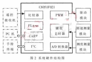
The overall structure of the micro turbojet engine computer control system is shown in Figure 1.
The controller receives the thrust and start and stop commands in the form of PCM (Pulse Coding Modulation) issued by the remote control receiver (or the host computer), and drives the servos such as the oil pump, the oil valve, and the igniter to measure the temperature of the engine in real time. The speed is completed, and the control functions such as auto-ignition, acceleration, deceleration, speed stability, over-temperature and over-speed protection are completed, and the status parameters are sent to the PC in real time through the RS232 bus. System parameters can be modified through the handheld terminal.
In order to facilitate system debugging and test engine performance, the real-time detection software ECU1.0 (Engine Control Unit, Version 1.0) running on the Windows platform was also developed.
1 hardware design
The C8051F021 microcontroller is a high-performance 8-bit SOC microcontroller from Cygnal Corporation of the United States. Mainly have the following advantages:
(1) Adopting pipeline technology, the peak processing speed can reach 25MIPS, which is much higher than other 51 single-chip microcomputers.
(2) With 12-bit 8-channel successive comparison ADC, the data conversion rate can reach 100ksps.
(3) On-chip RAM of 4K bytes and Flash program memory of 64K bytes. In this application system, there is no need to expand the memory.
(4) Five programmable PWM control signals are available.
(5) Rich timer resources with five hardware timers.
(6) Provide I2C bus control module and two UART ports.
(7) On-chip FLASH supports IAP (programmable in application). Therefore, infrequently modified data such as configuration parameters, lookup tables, etc. can be directly stored in the FLASH on the chip without external expansion of the non-volatile memory.
C8051F021 single-chip microcomputer has a wealth of on-chip hardware resources and high computing speed. For this control system, it can meet the demand of hardware resources of control system with little margin. Figure 2 is a block diagram of the system hardware.
1.1 Speed ​​measurement module
The engine speed is measured using an infrared pair tube. A through hole is drilled in the shaft of the engine, and the connection of the transmitting-receiving pipe is passed through the hole during installation. The infrared receiver tube will conduct twice per revolution of the engine. Since the on and off states are gradual, and the ordinary infrared tube switching speed is low, when the engine is running at high speed (up to 120,000 RPM), the amplitude of the pulse signal output from the receiving tube is small, and the rising edge/falling edge is relatively gentle. The MCU cannot be accurately identified and must be shaped. The shaping circuit is shown in Figure 3.
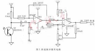
The signal is coupled to the non-inverting input of op amp AR1 via capacitor C6 (with a reference point of 2.5V) for high-magnification amplification to ensure that the peak-to-peak amplitude of the pulse is close to the 5V supply voltage even at high rotational speeds. The operational amplifier AR3 is used to implement the hysteresis comparator to improve the anti-interference ability, and its output signal is sent to the T4EX pin of the single chip microcomputer. The edge capture function of Timer 4 makes it easy to measure the time interval between adjacent pulses to convert the speed.
1.2 Temperature measurement module
The temperature inside the engine is an important indicator of safe and reliable operation of the engine. Due to the small size of the engine, the operating temperature of the engine is characterized by the temperature of the tail nozzle, taking into account the ease of assembly.
Tests have shown that the temperature of the tail nozzle can be as high as 900 °C. Nickel-chromium-nickel-silicon (Ni, Cr, Si) thermocouples are used as temperature measuring elements for temperature measurement range and cost considerations. The nickel-chromium-nickel silicon thermocouple has good linearity and the temperature range is from 0 to 1000 °C. Since the engine's temperature measurement accuracy requirements are not critical, thermistors are used for temperature compensation.
1.3 PWM driver module
The servo mechanism of the valve and igniter, starter motor and oil pump motor in the system is controlled by PWM mode. The starting current of the starting motor and gear pump is relatively large, up to 14A. A MOS tube with a large overcurrent and a small on-resistance or a Schottky diode with a small voltage drop should be used. This system uses a MOS tube with an overcurrent of 120A and an on-resistance of 7.5mΩ. However, tests have shown that the operating temperature of the MOS tube is still high, so two parallel drive modes are used. The schematic diagram of a PWM control unit is shown in Figure 4.
The main function of the resistor R6 is that when there is no control input signal (such as line fault, during reset of the microcontroller), the MOS transistor remains off and the servo mechanism does not operate. When the MOS transistor is turned on, the input capacitance of the MOS transistor is quickly charged through Q4; when turned off, the input capacitance of the MOS transistor is quickly discharged through D3 and Q3. By adopting the above circuit having a higher switching speed, the heat generation amount of the MOS tube can be effectively reduced.
1.4 system communication bus
I2C bus is low in cost, simple in connection, and has certain anti-interference ability. At the same time, it can connect multiple devices, so I2C bus is selected as the system communication bus. Handheld terminals and signal lights are connected to the system board through the I2C bus, and are driven by the serial-to-chip PCF8574.
2 system software
The system mainly completes engine control tasks and man-machine interface tasks. When using processor development software directly, these two task processing will be severely coupled due to the coexistence of time. In addition, the function call associated with the human machine interface must be designed to be non-blocking mode. Otherwise, when a fault such as an I2C bus occurs, the control flow cannot continue to execute downward.
RTOS can reasonably allocate processor resources, so that multiple tasks can achieve parallel operation in a macroscopic manner, which can greatly reduce the coupling between tasks and improve the reliability of the system. Even if a task is blocked for a long time, it will not affect other tasks. Therefore, software development using RTOS is simpler and more reliable. This system uses MicroStar RTOS V1.0 [3]. MicroStar RTOS is an embedded real-time operating system kernel designed for low- and mid-range microcontrollers. It also supports three scheduling strategies according to time slice rotation, priority preemption, and a combination of the two. It has perfect task management function to provide timing and delay services, support message and signal communication mechanism, and support critical code segments. Protection, providing binary, counting semaphore synchronization objects, etc., supports Bottom-half interrupt management mechanism.
The controller selects the preemptive scheduling policy according to the priority, and the system clock period is set to 2ms. A total of three user tasks have been created: the main interface of the human machine interface, the control tasks, and the communication tasks with the PC.
2.1 MicroStar RTOS transplantation on 51 MCU
Due to the reason of the 51 MCU core, the Keil C51 compiler uses some unique methods for code optimization, which is quite different from the ANSI C compiler. Therefore, compared with other hardware platforms, there are many modifications when porting MicroStar RTOS on 51 single-chip microcomputers, including the following categories:
(1) Keil C51 not only has data types, but also storage types, so a storage type modifier is added to system variables.
(2) By default, Keil C51 uses a static allocation strategy for temporary variables that are not allocated in registers. Many system functions are therefore not reentrant. You must add a reentrant function to these functions to force the compiler to allocate temporary variables in the simulation stack. .
(3) In addition to the hardware stack, the Keil C51 compiler implements the analog stack on the software, so the protection of the analog stack needs to be added to the stack protection.
(4) Modify the INITIAL_STACK task stack initialization macro in the os_cpu.h file, and rewrite the os_Schedule scheduling function. This is no different from other platforms.
2.2 Human Machine Interface Main Task
The main task of the man-machine interface is mainly responsible for system self-test, keyboard scanning, liquid crystal display, command analysis, etc. The flow chart is shown in Figure 5.
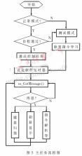
The main task has both test and normal operating modes. Test mode will be entered when a specific key is pressed at power-on or the system self-test fails. In the test mode, there are system parameter settings, pulse width command learning, and testing the permissions of each servo mechanism, but do not have the authority to run the engine. In normal mode, only the right to run the engine is available, but no parameters can be modified to reduce the risk of accidental rewriting of system parameters. Before activating the control task, the main task will perform software and hardware module checks including program code verification, configuration parameter verification, temperature sensor check, and the like. These measures can improve the reliability of the system.
MicroStar RTOS provides periodic timing services. The main task sets a 50ms keyboard scan timer and a 100ms LCD display refresh timer through os_SetTimer. When the time is up, the timer will send a message to the task. After calling os_GetMessage to get the message, the keyboard processing function and the display function are called to process the corresponding message separately.
2.3 Control tasks
A complete engine operation can be divided into several stages as shown in Figure 6. The control tasks are cycled through these phases, and an abnormal condition occurs in any of the phases, and the tasks are put into a parking state. The specific stage is:
(1) Standby phase. The state of the engine meets the operational requirements and waits for a start command entered in PCM code. It is stipulated that the pulse width corresponding to the cart command is the start command.
(2) Ignition phase. The motor speed fluctuates within the set upper and lower limits, the combustion-supporting butane gas valve is opened, and the combustible gas is injected into the engine body, and the igniter is turned on to heat the gas. When the gas is ignited to raise the temperature of the tail nozzle to a set value, it is considered The ignition was successful.
(3) The stage of driving. The oil pump starts to work, the oil supply is gradually increased, the igniter, the gas valve and the starter motor are turned off one after another, and the engine speed starts to accelerate. When the speed and temperature both exceed the set value, the car is considered successful.
(4) Hot car stage. After the engine is successfully driven, it is not advisable to put it into operation immediately, and it is necessary to continue running for a period of time in the idle (idle) state.
(5) Normal operation phase. The PID control algorithm is put into operation.
(6) Parking phase. When the oil pump stops running, the starting motor will intermittently turn on according to the temperature, and save energy as much as possible under the condition of facilitating heat dissipation of the engine.
3 control law design
According to the control content, the control items of the micro turbojet engine are divided into the following categories:
(1) Process control. The engine can complete the transient working state quickly, stably and reliably, including start control, acceleration control and deceleration control. Start control ensures normal engine ignition and smooth start. The purpose of the acceleration control is to change the fuel supply amount so that the acceleration time is as short as possible while the engine is not overheated. The deceleration control prevents the oil from being excessively oily when the throttle is closed, preventing the combustion chamber from being lean and extinguished.
(2) Thrust control. The goal is to provide the required thrust to the engine. The engine thrust is not easy to measure directly when the aircraft is flying in the air, but the engine speed can characterize the thrust of the engine, so the thrust control is realized by the speed control.
(3) Security control. The aim is to ensure that the engine works safely and reliably. Including over temperature protection, over speed protection, battery voltage under voltage protection.
3.1 Start control
The shorter the start-up time, the better, so the engine speed is faster. Simply increasing the fuel supply can increase the engine's growth rate, but it is easy to overheat due to excessive "rich oil." The phenomenon of "rich oil" means that when the fuel supply speed increases too fast, because the inertia of the engine is greater than the inertia of the oil pump, the engine speed increment is relatively backward, and the relative air volume of the intake air is insufficient, so that the fuel combustion is insufficient. The temperature inside the engine body will rise sharply, and a flame will appear in the exhaust gas, which is extremely harmful to the engine. In order to alleviate the "rich oil" phenomenon, temperature and heating rate feedback are introduced in the process control of the vehicle. When the temperature exceeds the warning value or the heating rate exceeds the warning value, the fuel supply will stop increasing.
3.2 Speed ​​control
The speed control adopts the positional digital PID control algorithm commonly used in engineering. For this system, the control amount is the PWM duty cycle of the oil pump. A negative duty cycle has no physical meaning. It is necessary to add a working point above the output of the PID to adjust the output up and down at the operating point. The speed control block diagram is shown in Figure 7.
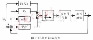
Among them, F(N0) is the working point generating function, which represents the reference value of the duty ratio corresponding to the commanded rotational speed N, that is, the working point, which is obtained through experiments. The software implementation uses the look-up table method and linear interpolation method. The limiting link ensures that the duty cycle of the oil pump is neither less than the duty cycle at idle, to avoid flameout; nor is it greater than the set maximum value to avoid the risk of overspeed. On the one hand, the throttle acceleration limiting section limits the refueling speed to prevent overheating due to too fast refueling; on the other hand, it limits the oil collection speed and prevents lean oil from being extinguished due to excessive oil collection. The throttle acceleration limit simply implements acceleration control and deceleration control.
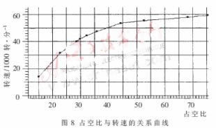
Due to the nonlinear relationship between the oil pump duty cycle and the engine speed (as shown in Figure 8), the segmented PID method is adopted, that is, different PID parameters are used in different stages. As far as Kp is concerned, it can be seen from the figure that in the low speed section, the slope of the curve is steep, the speed is sensitive to the change of the duty cycle, and the value of Kp is small, avoiding excessive overshoot and oscillation; In the segment, the curve rises very gently, and Kp takes a larger value to improve the response speed. Similarly, in order to achieve better performance, Ki and Kd should also take different values ​​in different speed segments. There are three segments in this system.
4 system test
This system has been tested several times. In the test, the controlled object selected a turbojet engine with a domestic 500-pulse thrust, and the raw data was obtained through the serial port using ECU V1.0 running on the PC platform.
4.1 Detection Software ECU V1.0
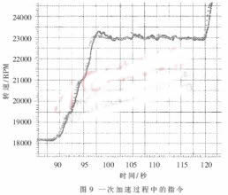
In order to facilitate system debugging and testing, the software ECU V1.0 was developed by itself. It can record various parameters of the engine in real time and display it dynamically in a curved way to analyze the correlation between various parameters, and has auxiliary functions such as sending control commands and alarms. Figures 8 and 9 are each generated by the software.
4.2 Test results
Tests have shown that the engine can track the speed remote command well under the control of the control system. Figure 9 shows the curve of the command and speed in a putter operation from 18000 RPM to 23000 RPM. The dotted line is the command and the solid line is the speed. The two curves are basically the same.
The micro turbojet engine control system is still a relatively new field in China, and the author has made a deeper exploration in this respect. In the test, the control system can work reliably and stably, reaching the level of the engineering prototype.
We make OBD connector with terminal by ourselves, soldering type and crimping type are both available. Also 12V and 24V type. OBD1, OB2, J1939, J1708, J1962, etc. Also molded by different type, straight type or right-angle type. The OBD connector cables used for Audi, Honda, Toyota, BWM, etc. We have wide range of materials source , also we can support customers to make a customized one to replace the original ones.
Vehicle Diagnostic Cables,Diagnostic OBD Cable,Heavy Vehicle Diagnostic Cables,OBD2 Splitter Y Cables,OBD2 Diagnostic Adapters,OBD Heavy Vehicle Cables
ETOP WIREHARNESS LIMITED , https://www.etopwireharness.com