Currently, each LED current that can be driven by the chip itself ranges from 25 mA to 100 mA. Of course, for some high current applications, we only need to use the external field effect tube to achieve.
LED is undoubtedly the hottest application at present. Whether it is handheld devices, game consoles, neon lights, billboards, etc., dazzling colors and high-quality light can always attract people's attention. In the face of many current LED controllers, how to choose a feature-rich and cost-effective product to cater to your own design is undoubtedly a problem for every designer.
The simplest LED driver, we can use ordinary I / O to achieve. However, the I/O control can only realize the ON and OFF of the LED, and cannot be used for functions such as mixing and flickering, and each LED needs to occupy a separate I/O resource, which is undoubtedly low in cost performance. We can also design with a dedicated high-current LED controller, but the expensive cost will first become a problem, and the design is complex, and the degree will be correspondingly increased with the occurrence of various interferences. Based on this, NXP has introduced a series of LED drivers using I2C interface, which can control ON/OFF, flicker and RGB mixed light from 4 to 24 LEDs simultaneously through two lines of I2C interface. . In a mixed-light scheme, each LED is driven by a separate 8-bit/256-order PWM.
This I2C-based LED control method increases the convenience and flexibility of the design, and also reduces the investment in hardware and software, making the LED in mysterious appearance seem simple and wonderful for us. Below, we will take the NXP LED driver PCA9633 as an example to explain the advantages of this LED driver through several simple applications.
The PCA9633 is a quad LED driver that can drive up to 25mA per channel and provides an optional fixed I2C address and a 4-bit or 7-bit hardware programmable hardware address, depending on the package. As shown below.
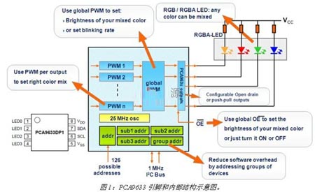
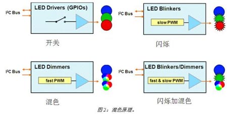
From Figure 1, we can see that each LED is controlled by a single 8-bit/256-order PWM, and because the PWM is fast enough, it can theoretically mix any color through the four LEDs it drives. Light. In addition to each individual PWM, the PCA9633 also provides a Group PWM, which allows us to control the brightness and frequency of the blended color, making up for some functions that only a single PWM can't. So how exactly does the PCA9633 implement dimming? The secret is still on the PWM. If you do not use PWM, then it can only complete the opening and closing action; low-speed PWM can only achieve LED flashing, not enough to achieve the purpose of color mixing; high-speed PWM can achieve RGB color mixing; if PWM speed is controllable, then Dual functions of flickering and color mixing can be achieved. And through the controllable 8bit/256-order PWM, the color gradation is increased to enhance the layering of color. See Figure 2 below.
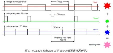
Knowing the principle of color mixing, how is a specific color produced? We know that the perception of color by the human eye is a superposition of the brightness averages of various colors. We can control the brightness of the driven LED by controlling the duty cycle of each PWM of the PCA9633. According to the principle of three primary colors, if we drive RGB (or RGBA) LEDs, then by adjusting the different brightness of these three LEDs, you can get the desired color. Figure 3 shows an example of the PCA9633 controlling three LEDs of RGB to adjust the pink light.
Through the above description, we basically know the internal structure and driving principle of PCA9633. Below we will use the PCA9633 fixed I2C address several applications to further understand the advantages of this LED controller.
For the first application, we will use the PCA9633 to control the brightness bar. We know that applications such as brightness bars often require a large number of LEDs to be connected in series. If a single interface is used to control each LED, the cost and software complexity will increase dramatically. With I2C, only two control lines are needed on the hardware, and only one byte command can be sent in the software, which makes it easy to control. In addition, due to the uniqueness of the I2C device address, several PCA9633 can be used to control the number of LEDs driven. If the driving current of the PCA9633 itself is not enough in practical applications, it is easy to solve by adding a FET to the periphery. In addition, the PCA9633's unique Group PWM makes it easy to control the intensity and flicker of the entire brightness bar. The following is a schematic diagram (see Figure 4), where the I2C master is provided by the system, either an MCU or a logic circuit.
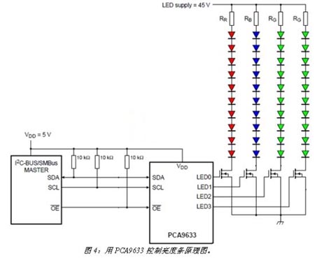
The left half of Figure 4 is the master of I2C and will not be described in detail. The top right side is the LED current limiting resistor. Usually, the forward voltage of the LED is about 3V. There are some differences depending on the color and manufacturing process. We can calculate the value of this current limiting resistor by the required LED current: R = (Vsupply - Vfsum) / If. If the required LED current is greater than 25mA, then the FET added in the figure can easily solve this problem. Once we have added the FET, simply set the OUTDRV of the corresponding register of the PCA9633 to high to distinguish it from its default value. Now we can see that using PCA9633 to control so many LEDs, the schematic is quite simple, and it is also convenient in the software setting register. The PCA9633 provides easy and complete internal registers such as LED output structure settings, power save mode settings, chip enable mode settings, LED output status settings, and control register settings for each PWM and Group PWM. In addition, PCA9633 also provides a register setting increment bit, which means that if we set this bit, then we can complete the order configuration of all internal registers through a sequence of instructions, which is in some specific applications. Very useful to maximize software and system resources savings. Below, we will illustrate the setting of the internal registers by another example.
The second example is the use of the PCA9633 to complete the function of the breathing light. Although the PCA9633 does not have a breathing light module inside, we can achieve this function through some simple register settings, which is a huge advantage in cost compared to a dedicated breathing light chip. For the sake of explanation, we only use PCA9633 to control the breathing action of an LED. The schematic diagram is very simple. It is omitted here to control the lightening and dimming process of this LED to achieve the purpose of breathing. To achieve this, the PCA9633's independent PWM will be the most important factor. As we have mentioned before, each LED is controlled by an 8-bit/256-order PWM. That is to say, each lamp has 256 segments of bright and dark color gradation, which can perfectly realize the breathing function. Specifically, we do this by controlling the duty cycle of the PWM. If our LED is controlled by PWM0 of PCA9633, the duty cycle of PWM0 will determine the brightness of this LED: Bright(duty cycle)=PWM0[7:0]/256.
At this point, a complete breathing process is completed, with a few simple register settings, it seems to be done only with complex systems or dedicated chips. From the above two examples, we can see that NXP's I2C LED driver is very simple and easy to operate, both in hardware and software, and the functions that can be realized with such devices are no better than some systems and The proprietary chip is inferior.
In summary, the I2C LED driver provides a cost-effective LED design that saves system resources compared to GPIO or dedicated LED drivers, while reducing the cost and complexity of the design and improving design reliability. The uniformity of the driving light. In addition, the use of such LED drivers can help us reduce design cycles and design flexibility.
The efficiency of radiator determine the performance of water cooling system directly, aluminum not only has excellent heat dissipation, but also has the smaller density,
aluminum radiator lighter than the same volume of copper radiator. The heat dissipation performance of radiator mainly depends on two aspects, one is the thickness, the other is the spacing of fins. The FPI (Fin Per Inch) value is used as a reference. And the matching of the fan is also very important.
Pure Aluminum Radiator,Aluminium Radiator,Aluminum Heating Radiators,Aluminum Cooling Radiators
Dongyuan Syscooling Technology Co., Ltd. , https://www.syscooling.com