The switching power supply for LED is a single-output AC-DC external power supply with a rated voltage not exceeding 600V, and the LED switching power supply for outdoor use is more severe than the indoor environment. Therefore, the LED switching power supply for outdoor use is selected as the LED power supply. The focus of the research is more representative.
The LED display research uses a dot matrix display with a screen of 8 & TImes;8, focusing on the dynamic processing method. Due to the limitations of the display screen, only English and numbers can be displayed in this research design. A basic LED screen consists of 8 rows & TImes; 8 columns of a total of 64 LEDs, the display has a common connection between the common and the common.
Design ideas
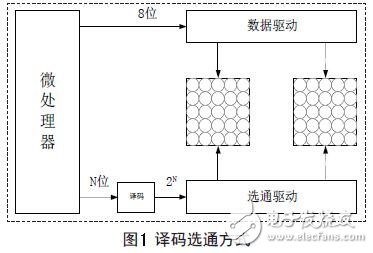
For an LED display consisting of 8&TImes;8 dot matrix, the general data terminal is connected to the 8-bit parallel data port of the microprocessor, and the strobe terminal is enabled (strobe) one by one to select a column to be lit. Dynamic display effect is achieved by time division multiplexing. There are two general strobe modes: independent strobe and decode strobe.
If the screen is small and the processor has enough I/O ports available, you can connect one strobe to each I/O port, as shown in Figure 1. If the screen is large, or the processor's I/O port is not Very rich, you can strobe by decoding, as shown in Figure 2. For example, when 8 pieces of 8&TImes; 8 dot matrix LEDs form an 8×128 dot matrix LED screen, the direct strobe mode requires 64 I/O ports, and the decoding strobe mode requires only 6 I/O ports.
Hardware circuit
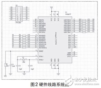
In the LED display system, an 8×8 display is used, so 8 strobe I/O ports are used, and the strobe mode adopts an independent strobe mode. The signal is supplied to the strobe through the I/O port of the software Atmega16. The Atmega16 does not need to be attached to its driver line, and the software atmega16 has direct drive capability. The circuit diagram of the display system is shown in Figure 2.
software design
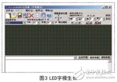
The characters displayed on the 8×8 dot matrix LED screen need to be converted into actual display data by means of modulo. This process can be realized by PctoLCD2002 software. As shown in Fig. 4, PctoLCD2002 is an LCD font generation software, which is also suitable for Font generation for dot matrix LED screens. The size of the English characters generated here is 8×8 dot matrix, and the mode of setting is set to cathode (lighting bit is 1), column by column and forward direction (high position first).
to sum up
By studying the display system of the LED display screen, focusing on the display dynamics of the LED screen, two timers are used to control the brightness of the display screen and the dynamic shift speed of the displayed characters. The schematic diagram of the LED screen display system is designed under DXP2004. The displayed characters can be taken by PctoLCD2002 software. In the design of the system, according to the actual LED screen type and circuit connection settings, the appropriate cathode mode is selected.
The use of LED switching power supply, applicable laws and regulations and standards, laid the foundation for evaluating and reviewing the design safety of new development products, scientifically and effectively monitoring product quality; actively responding to technical trade barriers, helping enterprises to improve quality management and quality control capabilities And the ability to deal with the broken wall has great guiding significance. At the same time, it provides a good first-hand reference for future national bureaus to research and formulate technical measures and regulatory measures for “green powerâ€, “green appliances†and other related products.
Magnetic Buzzer,Buzzer Magnet,Magnetic Buzzer Transducer,Magnetic Audio Transducer Buzzer
NINGBO SANCO ELECTRONICS CO., LTD. , https://www.sancobuzzer.com