introduction
Over the years, consumers have become accustomed to relying on the convenience and enhanced security provided by passive car anti-theft systems. This system consists of a key fob carried by the driver and a base station installed in the car. The two work together to determine whether the driver has the right to start the car; and more importantly, the system can prevent illegal users from using the car. Although on the surface, the functionality of the car alarm is very simple, but its basic implementation technology is very complicated and interesting. This article discusses the hardware and software issues of car alarms, and gives a noteworthy comment on design and security considerations.
Communication
At present, in the passive car anti-theft system, the main communication method between the key card and the car is to use a modulated magnetic field, which is generated by the car's anti-theft base station from low-frequency (generally 125 kHz) alternating current. There are three main uses of this magnetic field: A) The energy source of the key card, so it is called "passive" (passive); B) The carrier that transmits information from the base station to the key card (ie "downlink"); C) The carrier that transmits information from the key card to the base station (ie, "uplink").
Since the car anti-theft system needs to work completely passively (such as without batteries), the magnetic field characteristics of the key card are particularly suitable for this application. Both "downlink" field detection and "uplink" field modulation can be implemented with circuits that consume very little power. In addition, it is relatively easy to use the field energy of the saturation magnetic field to power these circuits in the key card.
During the system design stage, some key parameters must be carefully considered, such as the energy requirements of the key card (which will affect the antenna coil geometry and drive level), and the security of the verification process (which has a direct impact on the response time) . The following will elaborate on this one by one.
System interface
The system architecture of the automobile anti-theft device is divided into several extraction layers, each of which represents a different system interface. Figure 1 shows a visual representation of these layers.
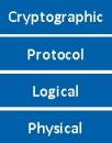
Figure 1 Automobile anti-theft device interface layering
Physical layer
The bottom layer of the car anti-theft system is the physical layer, which contains an antenna coil installed on the car, which can generate enough magnetic field to allow the antenna coil installed in the user's key card to be detected and modulated.
Magnetic field generation and modulation
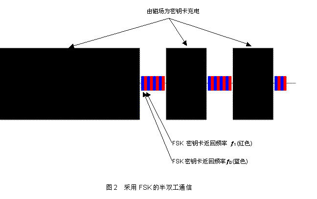
According to the different ways that magnetic fields support data transmission, car anti-theft systems can be divided into two categories: half-duplex and full-duplex. In a half-duplex system, the vehicle-mounted antenna coil alternates between energy transmission and data transmission cycles, and data modulation uses frequency shift keying (FSK). The diagram of this communication method is shown in Figure 2. Two points can be clearly seen from Figure 2: First, due to the need to repeatedly perform energy transmission, such as charging the key card, the data transmission rate is greatly reduced; Second, compared with the magnetic field during energy transmission, the modulated signal is extremely small Therefore, it is more susceptible to interference from ambient noise, resulting in a reduction in transmission distance. These characteristics make the half-duplex system gradually decline.
At present, the full-duplex system is mainly used. In this system, the vehicle antenna coil performs energy transmission and data transmission simultaneously, while data modulation uses amplitude shift keying (ASK). Figure 3 shows an illustration of this communication method. Obviously, the data transmission rate of this method is much better than the half-duplex system because it can synchronize data transmission and key card power supply or charging. Moreover, the constant carrier field can often shield the interference, ensuring the robustness and reliability of the communication during data transmission. In addition, this scheme can be implemented with a simple envelope detection circuit. In view of the current popularity of full-duplex automotive anti-theft systems on the market, these systems will be specifically discussed below.

System interface: logic layer
Above the physical layer is the logical layer. This layer deals with the characteristics and requirements of data transmission and encoding on magnetic fields. It applies to two-way data transmission from the car to the key card (often referred to as "downlink"), and from the key card to the car (referred to as "uplink").
Downlink
The downlink information is encoded using pulse length modulation: generally binary pulse length modulation (BPLM) or quad pulse length modulation (QPLM)). This method is based on inserting a fixed-length carrier field time slot "Tgap", and setting the time slot to time slot interval to a predetermined number of times: T0 corresponds to logic "0" and T1 corresponds to logic "1". The advantage of this scheme is that it embeds the energy transmission from the car to the key card into the data encoding, and ensures that the key card has enough energy to process the encoded data. However, this encoding method also has a disadvantage, that is, the data transmission baud rate must depend on the logical value of the data bit stream being sent, because the transmission time of each binary state is different. Figure 4 gives a more detailed illustration of this encoding method.
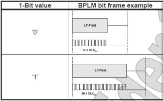
Figure 4 BPLM encoding method
QPLM is a variant of BPLM. With this modulation method, two bits are transmitted after a time slot, so more energy is available at the transceiver end. In addition, its average baud rate is higher than that of BPLM. This coding method is the same as the basic implementation principle of BPLM except that the allowed number of states is extended from 2 to 4, and the predetermined time slot interval is extended to cover more states. Figure 5 shows a visual representation of QPLM.
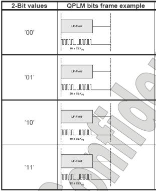
Figure 5 QPLM coding method
Uplink
The information communication from the user key card to the vehicle-mounted base station generally uses Manchester or Bi-phase encoding. These encoding methods share some characteristics that are different from the downlink: A) The average duty cycle of the encoded bit stream is always 50%; B) The time to send the encoded data depends only on the baud rate. Both of the above encoding techniques can extract clocks from the encoded data stream, because all time periods in the encoded bit stream are quantized to T or 2T (T means "half bit"). The data rate is fixed at 1 / (2T). Clock extraction only needs to detect the minimum time factor T and synchronize its phase with the encoded bit stream.
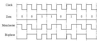
Figure 6 Manchester and Bi-phase encoding
Protocol layer
The protocol layer defines the grouping of various data bits to achieve communication between the vehicle-mounted base station and the key card. It defines how many bits there are, and in what order they are transmitted between the reader and transceiver. Using a simple analogy, this is similar to the grammatical rules of using words to form sentences. The protocol layer is like a sentence composed of a logical layer, and the logical layer is equivalent to a word. It forms a fixed set of commands and their allowed responses.
verification
Verification is a term used to describe the process of determining whether a driver has the right to start a car. The simplest form of authentication is called unilateral authentication (unilateral authenTIcaTIon). In this case, the car "tests" the key card to determine whether it matches the car. If an additional step is added to this process, that is, let the key "test" the car to determine whether it matches, then it becomes a two-way or interactive verification. Obviously, this additional step increases the security strength, but at the cost of longer verification time.
One-way authentication
Generally speaking, the one-way verification protocol is initiated by the car and includes the following steps:
1) The car reads the unique ID of the key card (not to be confused with the key)
2) The car generates a random number challenge (challenge) and sends it to the key card
3) The key card encrypts the query (using the key), and then sends a response to the car (response)
4) The response of the car to the key card is compared with the response calculated by itself (using the same key and query)
Note: The car must have the key card key for this process to be successfully completed. The process of sharing keys is called "Key Learn" and will be explained in detail in the next section.
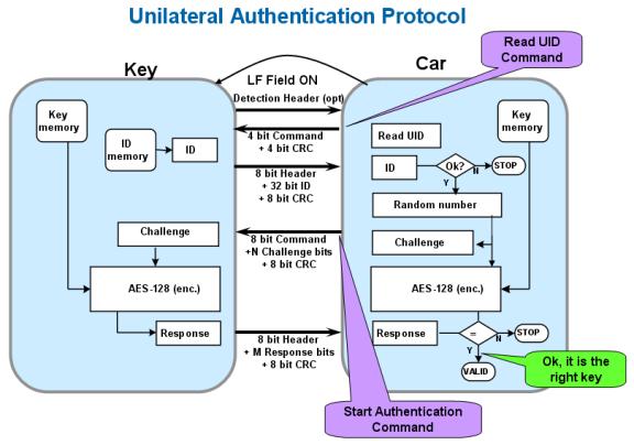
Figure 7 One-way verification
Key Learn: Public / Private
The Key Learn protocol refers to the process of making the car set up a key and share it with the key card. The key can be public or private according to the restrictions and security settings of the Key Learn session initiated by the car.
A public Key Learn process generally includes the following (and shown in Figure 8) steps:
1) The car generates a key based on the random number and submits it to the key card
2) The key card "accepts" the key, saves it in the memory, and responds (acknowledgment)
3) After successfully receiving the response from the key card, the car saves the key in memory
If the Key Learn protocol cannot stop eavesdroppers or protect the car from illegal use, then a private Key Learn process is required.
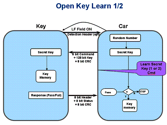
Figure 8 Public Key Learn
Two-way or quasi-interactive verification
Quasi-interactive or two-way verification is a more complicated verification process. The Atmel anti-theft system does not implement fully interactive verification because it does not use random generators at both ends of the system (car and key card). This implementation uses a message authentication code (Message AuthenTIcaTIon Code, MAC) to verify whether the car matches the key.
Moreover, in the case of two-way verification, the verification protocol is initiated by the car and includes the following (and shown in Figure 9) steps:
1) The car reads the unique ID of the key card
2) The car generates a random number query and sends it to the key card
3) The car encrypts the random number and attaches it to the query
4) The key card encrypts the query (using key 1) and compares it with the encrypted query received (MAC)
5) If the result matches, the key card encrypts it (using key 2) and sends a response to the car
6) The response of the car to the key card is compared with the response calculated by itself (using the same key and query)
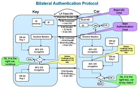
Figure 9 Two-way authentication
Encryption layer
The top layer is the encryption layer. This layer contains mathematical functions that convert plain text information into encrypted information. This function should ideally have two characteristics:
1. Uniqueness: For each plain text input, there must be a unique encrypted text output
2. Unpredictability: The plain text to encrypted text pair must be unpredictable, even if there are known plain text to encrypted text pairs for analysis.
Public and private
Private encryption algorithms have been popular for many years. However, the private algorithm has several deficiencies: A) The strength of the algorithm is uncertain; B) The lack of key code peer evaluation mechanism constraints; C) If the algorithm leaks, it may cause a large-scale security damage. In recent years, many eye-catching examples have been reported one after another, enough to illustrate the existence of these shortcomings. A more noticeable disadvantage may be that the system lacks interoperability and cannot share the same physical and logical layer. This hinders basic market competitiveness, and in many cases promotes system cost increases.
In order to solve these problems, people began to turn to the public domain encryption algorithm-advanced encryption standard (often called AES). This algorithm originated from the 1997 National Institute of Standards and Technology (NIST) initiative to solicit public domain encryption algorithms. A total of 15 candidate algorithms were produced that year, and all of them have undergone critical reviews in the field of encryption research. This evaluation analysis includes evaluation of the security and efficiency of each algorithm. NIST selected 4 of the 15 candidate algorithms, then entered the second round of public evaluation, and finally selected the AES algorithm in 2000.
As we now know, AES is a symmetric block cipher that uses 128-bit plain text input and 128-bit key to produce 128-bit encrypted output. Because of this symmetrical nature, AES can also operate in reverse, using the encrypted output and key to find and extract the original plain text input.
System security considerations-attacks and countermeasures
At present, there is a common misconception that the security of automobile anti-theft systems depends on the strength of encryption algorithms. Although the strength of the encryption algorithm is very important, but it does not determine the anti-attack ability of the entire system. Each interface, algorithm, protocol, logic, and physical characteristics in the anti-theft system affect the overall security of the system, and should be studied and enhanced to improve the system's resistance to attack.
Algorithm security and countermeasures
As mentioned earlier, encryption algorithms must have unique and unpredictable characteristics. Taking AES as an example, the detailed working principle of the algorithm is completely open to the public. Therefore, it has passed rigorous evaluation in the research field. This is by far the best countermeasure. So far, scientific research has confirmed the strength of the algorithm, and it has stood the test of more than 10 years. However, in the case of private algorithms, scientific analysis is impossible in the research field, and the strength of these algorithms is unknown. In fact, many of these algorithms cannot stand the test of time, and their shortcomings have been exposed in recent years.
Protocol security and countermeasures
In a system using one-way authentication, the attack on the protocol layer is generally a "scanning" or "dictionary" method. In a "scanning" attack, the attacker receives a "challenge" from the car and returns a random value in response. If the protocol contains a 56-bit response, the bit security is 256, that is, 256 attempts are required to obtain a correct "question-response" pairing. In order to prevent such attacks, the following measures may be considered:
Increase the bit length of the response to increase complexity
Let the time period between failed attempts to embed a car grow exponentially
After a certain number of consecutive attempts failed, let the car refuse to try
In a "dictionary" attack, the attacker collects the correct challenge (from the attacker) and the response (from the key card) by communicating directly with the transceiver. These "question-response" pairs are placed in a look-up table or "dictionary" for future reference. When equipped with such a dictionary, the attacker triggers the car to issue an inquiry, and then searches the dictionary for the corresponding correct response. If the protocol contains a 100-bit response, 251 attempts are required to obtain a correct query-response pair. "Birthday paradox" shows that after 2n / 2 records of "question-response" pairing and 2n / 2 attempts, the probability of getting the correct result is 0.5. It can be seen that the overall complexity of this attack is 2n / 2 + 1 = 251. The countermeasures that should be considered in this case are:
Increase the bit length of the query to increase complexity
Use two-way authentication protocol
Physical / logical security and countermeasures
In recent years, attacks have become increasingly sophisticated and advanced. "Side channel" attacks, such as Simple Power Analysis (SPA) and Differential Power Analysis (DPA) and other "intrusive" attacks, have been successfully used to extract keys from key fobs. These so-called side-channel attacks measure and evaluate the power consumption of encryption devices, and combined with the knowledge of plain text cipher text, an additional key can be extracted. The basic theory of these methods is quite complex and beyond the scope of this article. The most powerful measures to defend against these side channel attacks include:
Randomization of clock frequency and operation
Digital control and encryption work interleaved
"Intrusive" attacks focus on the physical implementation of encryption-related circuits on silicon chips. As long as the precautions are taken into account early in the design process, the realization of the best defense is fairly simple. Here are some examples of steps you can consider using:
Storage block metal shield
Use non-standard comprehensive library
Robbing the position of key digital elements used during encryption
In case of attempted intrusion, limit memory access and automatic chip erase function
System performance considerations
power consumption
System performance involves different aspects. One is the power consumption of the key card. This parameter is directly related to the communication distance between the available key card and the vehicle-mounted base station. Auto manufacturers and leading suppliers often emphasize the importance of coupling factors as a key parameter. However, it mainly describes the mechanical size relationship between the key card antenna and the vehicle-mounted base station antenna. This parameter is only valid for a given system configuration and depends on the antenna inductance, Q factor, drive current, reader sensitivity, and ignition lock core material. In view of this, it is not enough to use this parameter alone to compare the performance of different systems. In fact, in addition to the coupling factor, power consumption is also important, especially considering that the key card works in a passive and batteryless environment, the energy needs to be collected from the magnetic field and stored in a small capacitor Power consumption is very limited. By choosing ultra-low-power system components and a microcontroller that can be programmed with equalization software (as much as possible to put the microcontroller into sleep mode), engineers can overcome the aforementioned need for a high coupling factor to compensate the key The system defect of high current.
Verify response time
Another important factor in the anti-theft system is the time from turning the key card inserted into the door lock to starting the engine. This time should be short enough so that the driver does not feel the delay. Depending on the mechanical and electrical design of the system and the speed at which a person inserts and turns the key, the time budget should generally be between 300ms and 500ms. A considerable portion of this budget is consumed by the cost of machinery and body control modules; the remaining 100ms to 200ms are used for the verification process. In terms of speed and security, a good compromise is to use two-way authentication with a query bit length of 100 bits and a response length of 56 bits. In most systems, this will reduce the response time to less than 100ms.
Error handling
In order to prevent verification from failing for any reason, the current system needs a complete verification cycle to restart from the beginning, and only a maximum of 3 retries are allowed within a certain period of time. Atmel's retry strategy is slightly different, it can make the system recover from communication errors faster. All commands and optional data are protected by cyclic redundancy check (CRC). Both the key card and the base station use CRC to detect errors and signal these statuses to their respective communication partners. This allows the base station to choose the number of repeated messages, the last action, the last response, or the last command. This feature enables faster communication recovery, and allows more communication recovery attempts in the same time (5-7 retry attempts, not just 3)
to sum up
By selecting system components that meet the security and performance goals of the automotive market and support a highly configurable open source anti-theft software stack, the task of developing a robust automotive anti-theft system can be greatly simplified. As a leading manufacturer of automotive access solutions, Atmel has a complete system solution including hardware and software.
The key card design can be implemented using ATA5580 and ATA5795. Both devices include an LF front end, an AES hardware module that performs fast and efficient encryption calculations, and an AVR microcontroller optimized for ultra-low power consumption. They also contain programmable flash memory, which can be used to run Atmel's open anti-theft device protocol or other customer-specific software, and can make the anti-theft device completely passive.
Car base stations can be implemented with Atmel ATA5272. The device integrates LF base station functions and an AVR microcontroller with 8K programmable flash memory.
In addition to these devices, Atmel also provides users with free open anti-theft device protocol software, which can provide unprecedented highest user configurability (including many user-selectable functions that enable dynamic evaluation of system parameter trade-offs) Speed ​​up the development and optimization process:
Logic layer with uplink and downlink baud rate, bit coding and modulation depth
Protocol layer with challenge and reply bit length, one-way or two-way verification, data field CRC, two keys, private or public Key Learn
AES encryption clock speed "online" encryption layer from 125 kHz to 4 MHz
MOSO provides a wide range of IP67 Outdoor LED Driver supporting 0-10V, PWM, resistor and DALI dimming from 25W to 320W. All MOSO led driver for street lighting use aluminum metal case and are fully glue-potted for good dissipation. Surge protection is also built in outdoor led driver to protect street lights from lightning.


To meet different demand from different market, MOSO developed several series outdoor led driver supporting 108-305Vac, 90-305Vac, 249-528Vac different input ranges and got global certificates like CE, TUV, UL, ENEC, SAA, BIS, KC, etc..
MOSO has set several distributors in Europe, United States, Latin America, Asia and Australia. All MOSO outdoor led driver provide 5 years global warranty. In case of any failure, customers can get replacement either from MOSO directly or any one of MOSO distributors.
MOSO always dedicates to providing professional outdoor lighting solutions. Please feel free to contact our sales team if you need any support!
Street Light LED Driver,Outdoor LED Driver,Waterproof Street Light LED Driver,Quality Street Light LED Driver
Moso Electronics , https://www.mosoleddriver.com