With the development of social economy, anti-theft has become a growing concern of people. Iron gates and the like have not been able to bring too much security to people, and the demand for alarm equipment in the society is increasingly urgent. The intelligent alarm system is a technical prevention system established for the purpose of ensuring safety. He includes the timely detection of invasion and destruction by modern physics and electronic technology, the generation of sound and light alarms to deter criminals and reminding duty personnel to take appropriate precautions. In this paper, an acoustic alarm and an infrared sensor are used to easily design an indoor anti-theft device for offices, warehouses, shops and school rooms.
This article refers to the address: http://
1 hardware composition
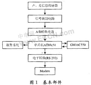
The hardware part of the alarm is composed of 8 basic components as shown in Figure 1, which can be divided into 2 modules. Among them, the sensor, the signal modulation circuit and the A/D conversion circuit constitute a signal acquisition module. The sound and infrared signals in the equipment room are converted into electric signals by sensors, and the signals are amplified and filtered in the signal modulation circuit, and then converted into digital signals by the A/D conversion circuit. The other module is the main body of the alarm, which consists of a single-chip microcomputer and an audible and visual alarm system, a GM16C550 serial port expansion chip and an RS 232 level conversion circuit. The single-chip microcomputer realizes the sound and light alarm function. The GM16C550 serial port expansion chip and the RS 232 level conversion circuit together with the single-chip microcomputer realize the communication between the alarm device and the school network duty center through the Modem, so that the relevant staff can discover and process the situation of the equipment room in time.
1.1 Sound and photoelectric signal acquisition module
Because the theft is generally happening at night, the anti-theft system usually makes the night design. In this design, the sound and infrared rays in the room are selected as the acquisition signals, so the integrated sound sensor PS-2109 and the infrared sensor BH are used as the acquisition system. Sensitive components.
The night room should be very quiet, set a noise level of the highest decibel (generally between 30 and 40 dB), the sound sensor will signal if the noise in the equipment room exceeds the preset limit. When someone or other animal enters the room, infrared rays are generated and the infrared sensor also emits a signal.
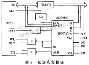
The circuit diagram of the data acquisition module is shown in Figure 2. The A/D conversion circuit uses the commonly used 8-bit 8-channel digital-to-analog conversion chip ADC0809. The output terminals of the sound and infrared sensors are respectively connected to IN0 and IN1 of ADC0809. It can be seen from Fig. 2 that the channel selection addresses A, B, and C of ADC0809 are respectively provided by the address latches 74LS373 of P89 to P0.2 of 89C51. When P2.7 = 0, ADC0809 is strobed together with the write signal WR. In Figure 2, the ALE signal is tied to the ST signal, the address signal is written at the leading edge of the WR signal, and the conversion is initiated at the trailing edge. For example, when the output address is 7FF8H, the channel IN0 can be selected to convert the analog quantity of the sound sensor output; the output address 7FF9H is the optional channel IN1, which realizes the conversion of the analog quantity output by the infrared sensor. In Figure 2, ADC0809's conversion end status signal EOC is connected to the INT1 pin of 89C51. When A/D conversion is completed, EOC goes high, indicating that the conversion is completed and an interrupt is generated. In the interrupt service routine, the converted data is sent to the specified storage unit.
1.2 Alarm Body Module
The sound and light alarm circuit is controlled by the single-chip microcomputer P3.7 port, and outputs an alarm signal (pulse signal with a high and low interval of 1 s) to drive the sound and light alarm circuit until the reset button RESET and the switch key are pressed.
The sound and light alarm circuit is composed of 555 timer, speaker and ordinary light-emitting diode. The circuit diagram is shown in Figure 3.
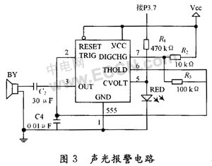
The 555 timer is connected to a low-frequency multi-vibrator, and its control voltage input and output terminal 5 is connected with the P3.7 terminal of the single-chip AT89C51, and is controlled by the pulse signal outputted by the P3.7 pin. By the charging and discharging action of the capacitor C4, when P3.7=1, the oscillation frequency of the 555 output pulse is low, and when P3.7=0, the oscillation frequency of the 555 output pulse is higher. The pulse signal is applied to the speaker via the blocking capacitor C2, and the speaker will emit two kinds of high and low alternating sounds, and the pulse signal of the high and low level interval of 1 s outputted by the P3.7 pin is applied to the LED through the resistor R1. On the top, the LED will flash and illuminate to achieve the effect of sound and light alarm at the same time.
When the alarm detects the abnormal information in the room, in addition to generating the sound and light alarm signal in the computer room, the on-site information needs to be notified to the on-duty personnel. To this end, the system is designed with a single-chip microcomputer and Modem communication module, which consists of a single-chip microcomputer, GM16C550 serial port expansion chip and RS 232 level conversion circuit.
2 programming part
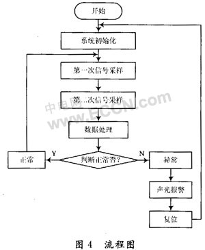
The monitoring program flow chart is shown in Figure 4. After the system is reset, it must first be initialized, including initialization of each control register, setting the entry address of the interrupt service routine, setting the stack, and so on.
The program design of the data acquisition part includes: driving the input terminals IN0 and IN1 of ADC0809 for A/D conversion, which are respectively completed by subroutine ADC1 (noise control) and ADC2 (photoelectric signal conversion);
The MCU receives the converted data and stores it in the specified memory unit, which is completed by the INT1 interrupt service routine. Wait for external interrupt 1 after each drive A/D conversion. The interrupt comes to indicate that the A/D conversion has been completed, and the converted data is read by the interrupt service routine.
3 Conclusion
The automatic alarm system of the indoor anti-theft features: alarms for sudden changes in indoor sounds and suspicious objects; if a hardware failure occurs (such as sensor drop, internal component damage, etc.), a fault alarm can be issued; if there is only one If the parameter is abnormal (such as excessive noise or the infrared sensor detects an abnormal signal), an abnormal alarm signal can be issued to enable the on-duty personnel to go to the site for processing; if the sound sensor and the infrared sensor simultaneously send an abnormal signal, it indicates that there is a thief and theft is issued. Alert and report this information to the duty room in a timely manner.
Rectifier Diode(Standard Diode) utilizes the unidirectional conductivity of the diode, which can convert the alternating current of alternating direction to a pulsating direct current of a single direction. Rectifier diode – diode designed for rectifying alternating current (mostly with low power frequency – 50 Hz at high power emitted during load). The main task of the rectifier diode is to convert AC voltage into DC voltage through application in rectifier bridges. The variant of rectifier diodewith the Schottky barrier is particularly valued in digital electronics.
")
Rectifier Diode(Standard Diode)
Rectifier Diode,Standard Diode,High Power Rectifier Diode,High Voltage Rectifier Diode
YANGZHOU POSITIONING TECH CO., LTD. , http://www.yzpst.com