The following questions should be noted when designing a battery-powered headset circuit:
This article refers to the address: http://
· Low supply voltage has sufficient output power;
· Rich sound quality - low distortion, high signal to noise ratio, and gentle frequency response.
A higher output voltage swing can be achieved with a bridge amplifier circuit with low distortion and high signal-to-noise ratio. Choosing the right amplifier chip and controlling the low frequency response eliminates the DC blocking capacitor in the output circuit. Unfortunately, the left and right transducers of the headset share the same common line, and this common pair is a barrier to bridge amplifier connections.
The circuit shown in Figure 1 allows DC-coupled stereo headphones to be driven with a common line from the bridge circuit. This circuit is based on TI's TPA152 amplifier.
For the circuit of Figure 1, the following equation can be given:
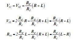
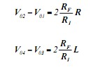
Where R and L are the input voltages of the right and left channels, respectively. The operating voltage of the earphone is equivalent to the voltage difference between V02 and V01 and between V4 and V3:
For component selection and data of the circuit, please refer to the TPA152 data sheet, RO=0.1RL.
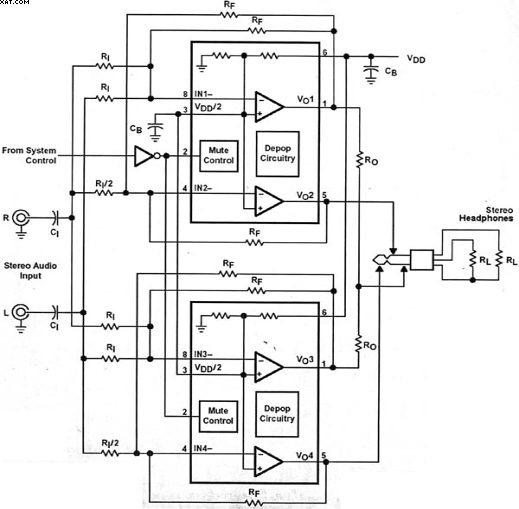
Figure 1 Two-piece headphone chip and a small number of passive components drive DC-coupled stereo headphones with a common line from the bridge circuit
Ni-Cd Battery Packs,Power Bank ,Portable Charger ,Portable Phone Charger
Storage Battery Co., Ltd. , http://www.battery-spark-e.com