The SD card is used to realize the design of car CAN bus data. The implementation method of SD card FAT file system based on LPC2368 is introduced. The hardware interface and software implementation of the design are given. The SD card is applied to large capacity. The advantages of data logging.
Key words: CAN bus; SD card; FAT file system; data recording
This article refers to the address: http://
The CAN bus is a serial data communication protocol developed by BOSCH in Germany in the early 1980s to solve the data exchange between many control and test instruments in modern automobiles. Its short-frame data structure, non-destructive bus arbitration technology and flexible communication methods adapt to the real-time and reliability requirements of automobiles, and are favored by automobile manufacturers. At present, the ECU (Electronic Control Unit) on the vehicle communicates using the CAN bus, such as an electronically controlled fuel injection system, an electronically controlled transmission system, an anti-lock braking system (ABS), and an anti-skid control system (ASR). The data on the CAN bus of the car is of great significance for monitoring the correct communication between the car ECUs and studying the causes of the car CAN network failure.
Designed with SD card as storage carrier, it realizes real-time recording of data on CAN bus. It has the characteristics of large capacity, small size, light weight and simple interface circuit. And the recorded data files can be identified by the PC, analyzed and played back by the analysis software on the PC, and used as historical data for data comparison.
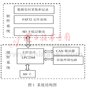
1 system design SD card used in the CAN bus data recorder system structure diagram shown in Figure 1, CAN bus data instrument should be attached to the car CAN bus when working, to become a CAN node, in order to collect CAN data information. The main function of the main control chip is to collect data and store the collected CAN data in a file format on the SD card. In addition, the SD card is compatible with the PC format in the data organization structure. The FAT32 file system is used here, so that the recorded data can be directly used by the application under the Windows operating system.
2 hardware interface design
The control core of the hardware platform uses NXP's ARM7 chip LPC2368, which is a 32-bit microcontroller based on the ARM7TDMI-S core. It can operate at frequencies up to 72 MHz, powerful and low cost, with up to 512 KB slices. Internal Flash, 32 KB SRAM, internal rich system peripheral controllers, including SD controllers and CAN controllers.
The SD card supports two working modes: SD mode and SPI mode. The SD mode allows 4-wire high-speed data transfer. The SPI mode allows a simple and versatile SPI channel interface, but the read/write speed is greatly reduced. Due to the high data transfer rate of the CAN bus, this design uses the 4-wire high-speed data transmission function of the SD mode.
LPC2368 and SD card interface circuit shown in Figure 2, using SD communication protocol to connect SD and LPC2368 for data transmission. CMD transmits the command of the SD controller and related parameters and the response signal of the SD card to the command. DAT0, DAT1, DAT2, DAT3 transmit and read data, CLK is the clock signal, and the main control chip controls the power of the SD card.

3 software design
3.1 SD card low-level read and write SD card read and write operations are based on the command, the main control chip to send the corresponding command to the SD card and read the corresponding response to achieve control of the SD card, before reading and writing to the SD card First, the SD controller should be initialized to complete the configuration of various parameters, including the DMA mode of the controller and CPU data transfer, the transfer rate, and the length of the read and write data block. After that, the SD card needs to be initialized. This is to ensure SD. The premise of normal data reading and writing. The initialization process of the SD card is shown in Figure 3.
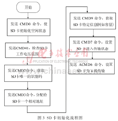
If the default block read/write length (512 B) is to be used after the SD card is initialized, the SD card can be read and written. Of course, the CMD16 command can also be used to set the block read/write length of the SD card, which can be any value between 1B and 512B. However, the writing process for the SD card requires that the block length be 512 B. Whether it is reading or writing of the SD card, it is required to have a data start token FEH after the read/write command is sent, and a cyclic redundancy coded CRC of 2 B at the end of the data transmission. This design uses the default block read and write length.
3.2 FAT32 File System <br> The data stored in the SD card is binary data. In order to make it recognized by the computer, the SD card file system must be consistent with the file system of the computer. Currently, the most commonly used file systems in the Windows family of operating systems are FAT16, FAT32, and NTFS. Due to the large amount of data in the car CAN network, and the recorder needs to record long-term data, this design selects FAT32 as the file system of the SD card. FAT32 supports a maximum of 4 GB capacity of a single file, meeting the requirements of the CAN data logger.
The FAT32 file system consists of four parts: the system boot record area, the FAT table area, the file registration table area, and the data area. The system boot record area stores the structure information of the SD card related to the disk, including the number of sector bytes, the number of FAT tables, and the total number of sectors; the FAT table is used for indexing and positioning of disk data (files) in the FAT32 file system. A chained structure that accurately records the clusters that have been occupied and indicates the cluster number of the next cluster that stores the subsequent content for each occupied cluster. The file registration table FDT records the entries of the file, each entry occupies 32 B, records the starting cluster number, size of the file, and the time of creation and last modification; the data area is used to store file data.
The main functions of the SD card's file system include creating files, opening files, writing files, reading files, and closing files. In the application, the above functions can be added or deleted according to the actual situation to simplify the system.
Considering the real-time requirements of data acquisition, simplifying the chain structure of the FAT table area, the free space of the disk is continuous, and adopting the continuous storage mode, thus omitting the process of searching for the free cluster every time the FAT table is searched, which satisfies The system's requirements for real-time performance. The simplified chain structure is a linear chain, that is, writing a sector automatically writes a sector, and writing a cluster automatically writes a cluster.
3.2.1 File creation
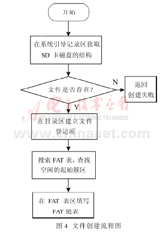
Creating a file on the SD card is a process of applying for an entry in the file directory table FDT and filling the free cluster number with the FAT entry in the FAT table. The flowchart is shown in FIG. The program first obtains the structure information of the SD card disk in the system boot record area; then it is detected whether the file already exists in the file registration table FDT, if there is a file with the same name, it returns, the file creation fails; then, the idle FDT entry is requested. After the FDT entry is successfully applied, the program will check whether the remaining space of the disk meets the needs of the length of the newly created file data, and then find the first free cluster number and modify the corresponding FDT entry. Since the files are continuous, the FAT list in the FAT table is a straight chain, that is, the previous cluster points to the next cluster. According to the size of the file, the FAT list is filled into the FAT table area until the last FAT item is written to 0x0FFFFFFFH, indicating that the file is End.
3.2.2 Reading/writing of files The files on the SD card are all accessed in clusters. When writing data to the files on the SD card, first find the file entries of the file according to the file name, according to the file entries. The starting cluster number in the file can find the first cluster in the data area, write data to the corresponding cluster in the data area, and find the second cluster number in the FAT table. According to the second cluster number, the data can be written to the second cluster and the third cluster number in the FAT is found, and so on, until the last item 0x0FFFFFFFH in the FAT table, the writing of the file is completed. The process of reading a file is similar to writing a file.
The application flow chart of the SD card in recording the CAN bus data of the car is shown in FIG. 5. The LPC2368 stores the received CAN data and the time of receiving in the data queue in an interrupt mode, and immediately jumps out of the interrupt, performs the processing of the main program or waits for the reception of the next frame of data to be interrupted, thereby avoiding the loss of the message.
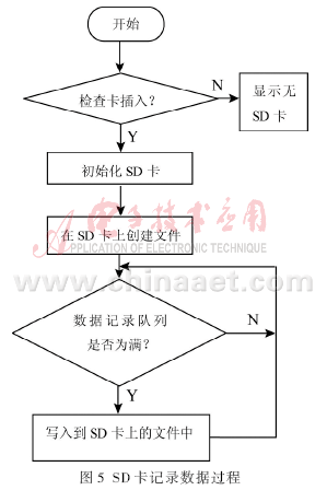
This design uses SD card as the external storage medium, and saves the CAN data information collected in real time in the SD card in the format of standard file. It has the characteristics of reliable performance, convenient use, light weight and large storage capacity, and has broad application prospects. .
Panasonic Feeder , the best price for the customers, original and new or used one, in stock.
Material: Stainless steel
Feeder can be divided into tape feeder, tube feeder, tray feeder or stick feeder.
Feeder can be divided into original feeder and replacement feeder.
All the feeders shall be maintained during the use time
I-Pulse Feeder
Smt I-Pulse Feeder
Pneumatic Feeder
FUJI Feeder
Smt Fuji Feeder
Smt Machine Feeder
Smt Tape Feeder
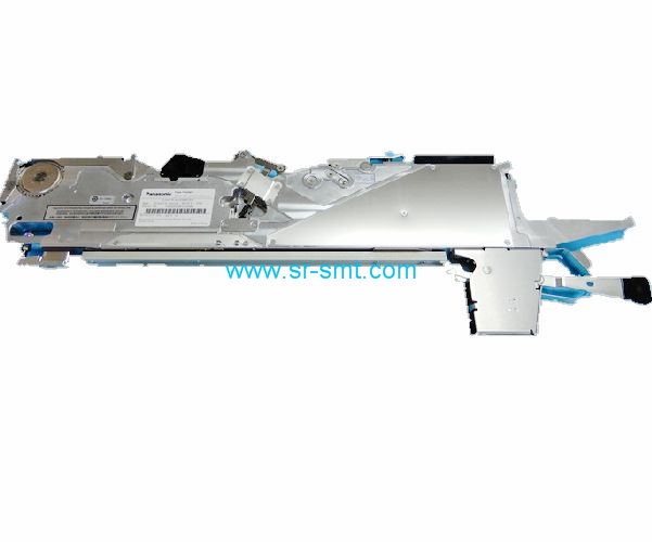
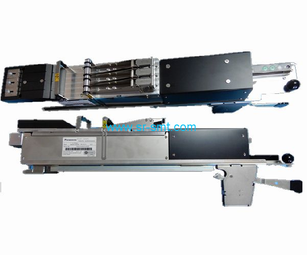
Panasonic Feeder
Panasonic Feeder,Panasonic Smt Feeder,Smt Machine Panasonic Feeder,Smt Feeder For Panasonic
Shenzhen Srisung Technology Co.,Limited , http://www.sr-smt.com