1 Introduction
This article refers to the address: http://
The standard specification for the digital video DVB-H (DigitalVideo Broadcasting-Handheld) system [1] is mainly based on the architecture of the terrestrial broadcasting system DVB-T (Digital Video Broadcasting-Terrestrial), and new technical standards are added to make specifications. Since the DVB-T system utilizes the multi-carrier modulation technique of Coded Orthogonal Frequency Division Multiplexing (COFDM), it can provide effective processing for the interference and attenuation problems caused by the multi-path reflection effect. With suppression capabilities, it is ideal for use in mobile applications. In addition, the DVB-H system standard has additional functions and improved technologies: DVB-H Transmission Parameter Signaling (TPS), Time Slice (TimeSlicing), SoftHandover (SoftHandover) algorithm, 4K mode, depth. In-depth symbol interleaver and Multi-Protocol Encapsulation Forward Error Correction (MPE-FEC) technologies are used to improve the mobile reception performance of handheld devices and overcome power consumption problems. Conditions Access (CA) applications and Electronic Service Guide (ESG) and other functions to make the service content more complete and more secure.
2. Related technology research
Recently, the research article on the MPE-FEC mechanism of DVB-H mainly focuses on how to detect the error in the data in the transmission stream when the receiver is decapsulating, and how to provide the error required in the error correction decoding operation. Information and how to improve the ability of the enhanced MPE-FEC mechanism to detect errors.
At present, the methods for error detection and judgment of receiving data at the receiving end can be mainly divided into two categories. The main difference between the two types is that error detection and judgment are performed on different levels of encapsulation formats, one of which is The solution is performed when the stream stream packet is demultiplexed, and the other is performed when the Multi-Protocol Encapsulation (MPE) format is further solved. The recommended way in the DVB-H specification is to use the latter, mainly by using a loop. Cyclic Redundancy Check (CRC) to detect and judge data.
Further, in terms of providing error information required for the error correction decoding operation, there are different error correction decoding methods depending on the form of the error information provided. Most of the above two aspects of planning and design concepts have been integrated into a research article [2] and are mainly divided into five structures, and this study considers the design and implementation convenience, so the so-called TSE ( TransportStreamErasure) error detection method (that is, correctness judgment according to the error indicator field in the TS packet header), and the RS decoding part uses the Euclid method for RS error correction decoding. .
3. Introduction to the core technology of digital TV broadcasting system
3.1DVB-H transmission system structure and package format
The transmission system of DVB-H transmission IP service is shown in Figure 1. After the DVB-H service data is encapsulated into IP packets, it is encapsulated in the transport stream through the MPE mechanism, and simultaneously adds Time-Slicing information to other DVB-T TV programs (MPEG-2TVService) via the multiplexer. Multitasking into a larger transmission stream (also known as composite program stream, MultipleProgramTransportStream), and then into a wireless signal transmission, wherein the MPE, MPE-FEC and Time-Slicing mechanisms at the transmitting end are collectively referred to as DVB-HIP packaging. The IP-Encapsulator is called the DVB-HIP decapsulator (IP-Decapsulator), and the entire DVB-H encapsulation format is shown in Figure 2.

Figure 1 Transmission system of DVB-H transmission IP service [3]
When the video compression and other service data are encapsulated in a series, they will be encapsulated into a transport stream (TransportStream) packet format, and then the receiver will be sent to the underlying hardware for a Solomon code before the packet is modulated. Send a wireless signal. Relatively when the packet is received at the terminal, the Solomon decoding is performed once, and the decoded result is recorded in the packet header.
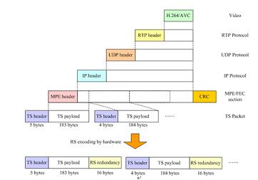
Figure 2 DVB-H data encapsulation format
3.2Time-Slicing transmission mechanism and time parameters
The purpose of the Time-Slicing transmission mechanism is to reduce the average energy consumption of the handheld terminal device and to implement a smooth handover between the SoftHandover mechanism and the base station. The Time-Slicing transmission mechanism is shown in Figure 3. It transmits data in an instantaneous high-rate pulse transmission (Burst).
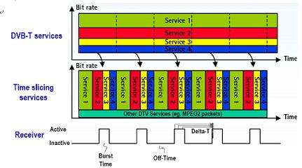
Figure 3 Burst transmission side of the Time-Slicing transmission mechanism
In addition, in order for the receiving device to correctly receive each Burst data, the time-stamped (Delta-T) information is included in Burst to indicate the arrival time of the next Burst (as shown in Figure 4), and the receiving end is premature. The Delta-TJitter time is used to open the receiver so that the data can be correctly received. The OffTime time between the two Bursts does not transmit any data, and the bandwidth sharing method is used to transfer data of other different services. The entire Burst has a maximum duration (MaxBurstDuration) when transmitting data and this information is also carried along the entire transport stream.
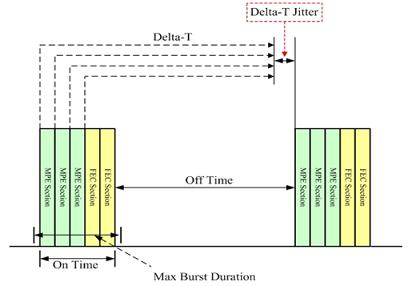
Figure 4 time parameter Delta-T schematic
3.3MPE-FEC mechanism principle and operation
The MPE-FEC mechanism is responsible for error data repair operations in the DVB-H system. The overall technology is built into a square memory device called the MPE-FEC framework. As shown in FIG. 5, the framework is further defined as two parts: ApplicationDataTable and RSDataTable, which are respectively used to store service data and error correction redundant coded data transmitted in the DVB-H system.
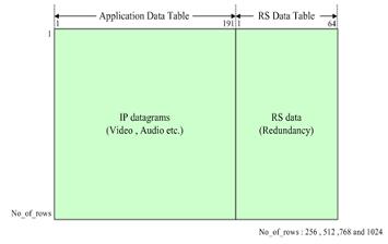
Figure 5 MPE-FEC framework
As shown in FIG. 6, at the transmitting end, the coding mode of the interleave coding is completed by vertically filling data and horizontal error correction coding, and then performing packet transmission. After receiving at the receiving end, the reverse error correction decoding operation is performed, thereby repairing data errors caused by the transmission.
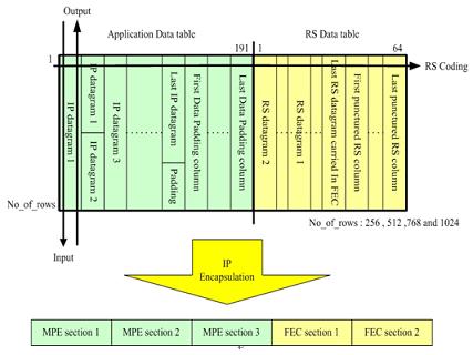
Figure 6 MPE-FEC frame interleaving coding
4, DVB-H software receiver system design
The detailed software architecture of the DVB-H receiver is presented in Figure 7. It is mainly composed of TransportStream Dispatcher, SubDecoder, Controller and MPE-FEC. FECOperationUnit).
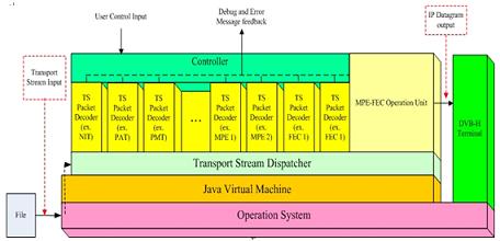
Figure 7 DVB-H receiver software architecture
4.1 Transport Stream Dispatcher
The transport stream dispatcher is mainly responsible for transferring various types of packets in the DVB-H transport stream to different sub-decoders for processing and filtering the programs to be viewed by the user from the packets to the DVB-H terminal device. . If during the Burst transmission, the packet data is corrupted due to noise interference, or the transmitting end adds some padding packets to the transmission bit rate of the service when transmitting, so in order to reduce the processing time of the packet, the packet is obtained in the transmission stream distributor. After that, it checks whether the stream packet has an error and whether it is a stuffing packet. If an error occurs, the packet is discarded, and the entire execution program enters the error classification mechanism (ErrorCategorizationmechanism), and if it is padded, it is discarded early. Avoiding unnecessary processing time is required to fill the packet into the sub-decoder. To simplify the complexity of the sub-decoder, the transport stream dispatcher uses the dispatch table method to register the type of packet sub-decoder to be decoded, and thereby separates the dependencies between the individual sub-decoders. Distributing a table uses an application of a hash table. The advantage of using a hash table is that the query time is always fixed to a constant value regardless of the number of registrations, so that the new form or TV station in the future specification will be widely supported. Customized private form. The dispatch processing action of the entire transport stream dispatcher is as shown in the virtual program code (Pseudocode) of Table 1.
Table 1 Virtual program code of the transport stream dispatcher
If System Start then
Set Buffer to receive TS packet
If ErrorIndicator is equal to 1
Drop this TS packet
Start Error Categorization mechanism
Else if PID is equal to 8191
Drop this TS packet
Else if PayloadUnitStartIndicator is equal to 1
If ContinueSection is not equal to Null
Call the sub-decoder to continue decode
Else
If sub-decoder is not found
Drop this unknown TS packet
Else
Call the sub-decoder to decode
Else
If ContinueSection is not equal to Null
Call the sub-decoder to continue decode
Else
Drop this TS packet
4.2 sub-decoder component
During the initialization period, the sub-decoder must register the packet type with the transport stream dispatcher to obtain the corresponding packet from the transport stream dispatcher.
Table 2 sub-decoder common virtual program code
Function:DecodeFunction
The first packet in the section is obtained from the transport stream dispatcher and decoded.
Set PayloadBuffer to receive the section data
Set PaylaodLength equal to PacketPayloadLength
If SectionHeaderLength is equal to 12
Decode the section header
If section payload is not equal to Null
Output section payload to
SectionPayloadCottectionUnit
Else
Set ReceiveLength equal to PayloadLength
Set ContinueSection to this sub-decoder
Function:ContinueFunction
The connected section packet data is obtained from the transport stream dispatcher.
Set PayloadBuffer to receive the section data
Set PayloadLength equal to PayloadLength add
ReceiveSectionPayloadLength
If SectionHeaderLength is equal to 12
Decode the section header
If section payload is not equal to Null
Output section payload to
SectionPayloadCottectionUnit
If PayloadLength is equal to SectionLength
Set ContinueSection to Null
Else
Set ContinueSection to this sub-decoder
The virtual program code common to the sub-decoder is as shown in Table 2. The transport stream dispatcher delivers the packet to the specific sub-decoder according to the already registered sub-decoder information in the dispatch table, and the sub-decoder is based on the packet. The data conveyed in the message releases the message or configuration and passes it to the controller object. When the sub-decoder knows that the section data length exceeds the number that can be carried by one packet by reading the length field of the section, the subsequent fragment pointer object setting is directed to itself. Thereafter, when the transport stream dispatcher receives the packet, it will check whether the contiguous segment pointer object is an empty object, and if it is an empty object, find the sub-decoder responsible for decoding the packet from the dispatch table. If the object is not empty, the packet is transmitted to the sub-decoder to be successively received, and after the entire section data is received, the sub-decoder will reset the contiguous segment pointer object to the empty object, and start from the next packet. The packet sub-decoder will be found in the normal procedure.
4.3 controller object
The controller object is the interface that the DVB-H software receiver interacts with the user. The main function of the controller is to implement the message output interface in addition to the user's input message. In the Control Behavior section, the controller interacts only with the sub-decoder, and in terms of message output, it is linked to all components in the entire DVB-H software receiver. In addition, the implementation design is different from the traditional method of embedding the control interface in the player, thereby achieving the independent capability of the DVB-H software receiver and the playback device.
4.4MPE-FEC arithmetic unit
The MPE-FEC operation unit is mainly responsible for the operation of the entire MPE-FEC mechanism. As shown in Fig. 8, it can be divided into three operation units: MPE section data collection unit, FEC section data collection unit and Solomon decoding unit (RSDecoding Unit). .
The MPE and FEC section data collection unit is mainly responsible for collecting the section data extracted from the sub-decoder, and when the section data is collected, it is filled in the MPE-FEC framework located in the Solomon decoding unit until all section data of the entire framework is completed. After the collection has been completed, the Solomon error correction decoding of each column is performed immediately, thereby repairing data errors caused by noise interference during transmission.
4.5 error generation, detection and classification mechanism
When the receiving end hardware receives the transport stream packet transmitted by the transmitting end, the hardware first performs a Solomon decoding on the packet. If it exceeds its error correction decoding capability, the error indicator field in the packet header will be ErrorIndicator) is set to 1 to indicate the packet in which the error occurred. This study is based on the value of this header field in the error detection judgment, and generates significant error data by setting the value of this field. To highlight the operation of the MPE-FEC mechanism. When an error packet is found, the error classification mechanism is immediately executed to find out which section of the entire section the error occurred and set to 1 in a corresponding position in the same size of ErrorBit-mapBuffer (EBB) as the MPE-FEC framework. Indicates its error location in the framework to provide the error location data needed for subsequent Solomon decoding, and the virtual program code for the entire error classification mechanism is shown in Table 3.
Table 3 error classification mechanism virtual program code
If ErrorIndicator is equal to 1
If HeaderDecoded is true
If error at middle of section
Set 1 in EBB according to the TS payload
Region of this section in MPE-FEC frame
Drop this TS packet
Else
If packet carry part of next section header
Set 1 in EBB according to the TS payload
Region of this section and whole the next
Section payload region in MPE-FEC
Frame
Drop this TS packet and drop all TS
Packets of next section
Else
Set 1 in EBB according to the TS
Payload region of this section in
MPE-FEC frame
Drop this packet
Else
Set 1 in EBB at whole section payload
Region in MPE-FEC frame
Drop all TS packets of this section
When the transport stream dispatcher receives the packet and immediately detects and determines whether the error indicator field in the packet header is 1, if it is 1, it indicates that an error has occurred and further starts to find out that the data sent by the error packet is located throughout. Which section location of the section occurs in the section header, because the header is the most important source of information for carrying the entire section, so in order to correctly receive the subsequent section, the error packet is included. When one byte of header information is used, the entire section data will be completely discarded and waiting for the next packet carrying the section header correctly. If the error packet is part other than the header information, it is further determined that the data range carried in the packet is in which section of the entire section data, and if only the middle part, only the packet is discarded. Waiting for the next correct packet, but if the data is at the end of the section, you need to further determine whether to include the next section header information, and if so, all the packets carrying the next section data. Discard and wait for the next packet that correctly carries the section header to come in. Otherwise, just discard the packet.
4.6Time-Slicing transmission mechanism design
The way DVB-H transmits data is to use Burst transmission mode. In this way, the arrival time of the next Burst and the maximum transmission time of transmitting the Burst data must be accurately known, so that the hardware can switch at the correct time. The receiver receives the data, and the receiver must meet two time requirements when receiving the data:
(1) When Burst arrives and receives the first MPE section for interpretation, the section header must be decoded within the Delta-TJitter time and the Delta-T value passed back to the physical layer.
(2) The IP decapsulator must complete the decoding of all sections and the operation of the MPE-FEC mechanism in the Delta-T time, and output the data to the terminal.
Since it is not always possible to interpret all section data in Burst's maximum maintenance time, the receiver must temporarily buffer all the section packets in the entire Burst time, and the decoding of the packet is completed in the remaining Delta-T time. Just fine.
In addition, since the buffer is used to temporarily store the section packet data during the processing, and the interpretation is taken out, the real-time Delta-T information carried in the header has expired, and only the first one is interpreted. The delay caused by the MPEsection is the shortest.
Therefore, in practice, the Delta-T information carried by the first MPE section header is used to inform the physical layer of the arrival time of the next Burst, and the Delta-T information in the remaining section headers will not be read. . The schematic diagram of the delay time of the entire section packet processing is presented in FIG.
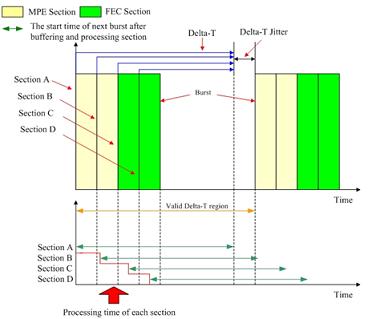
Figure 9 Schematic diagram of the delay time of the packet processing
5, experimental simulation results
The whole experimental simulation results of this study were tested by personal computer (PC). The personal computer is equipped as shown in Table 4. The transmission stream provided by the public video pilot program is regarded as the playback test file, while the table 5 is It is the information extracted from the streaming file mentioned in the public view.
5.1 correctness verification
The data verification after error correction in this study is completed by using the binary file comparison provided by the word processing software Ultra-Edit. Each Burst data and the corrected data added with errors are saved into a file and then compared with the verification file. Correct.
5.2 Effectiveness evaluation
The design of MPE architecture and Time-Slicing transmission mechanism in this paper mainly adopts the concept and architecture of [4]. In [4], the processing time of each Burst data (only for MPEsection) has quite complete analysis information. Therefore, this thesis is aimed at the performance analysis and discussion of the MPE-FEC error correction mechanism of the main design.
Table 4 Personal computer basic equipment table
Processor label specifications
Intel Pentium 4
Processor processing speed
3.0 GHz
Hard disk size
80 GBytes
Memory Capacity
512 MBytes
Table 5 public image source parameter data
parameter
Numerical value
File size
755,605,652 (bytes)
Total number of packets
4,019,179 (packet in 188 bytes)
MPE-FEC frame total number of columns
512 columns
Delta-T
1250 ms
Delta-T Jitter
7.5 ms
Maximum Burst duration
200 ms
Power saving efficiency
79.7%
Screen update rate per second
15 (frame per second,
In the entire transport stream file, the frame size of each Burst is 255×512, and the frame data size is 1Mbits (128kBytes). The number of RS error correction operations performed by each MPE-FEC frame is 512 times (that is, each One column performs one RS error correction operation), the code rate is 2/3, 10 Burst, 50 Burst and 100 Burst simply use Java and RS decoding uses Euclid algorithm to complete MPE on Windows. The average execution time of the -FEC error correction mechanism and the simple RS decoding is as shown in FIG.

Figure 13 Average execution time of the complete MPE-FEC mechanism operation and simple RS decoding
It can be seen from Fig. 13 that the operation time of the entire MPE-FEC mechanism is mostly spent on RS decoding. Therefore, this study further uses RS/C++ in RS decoding and uses JNI (Java Native Interface) call in Java using different decoding algorithms inside RS. Execute the complete MPE-FEC mechanism on Windows, and its execution results are presented in Figure 14.
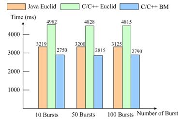
Figure 14: Average execution time of Java and C/C++ and different algorithms on Windows
Although in terms of execution time, the decoding time using C/C++ and using the BM algorithm is shorter, but for the Delta-T time (1250 ms) obtained in Table 5, the DVB-H receiver cannot be reached. Play in real time. Therefore, the C/C++ language execution time of different algorithms on the Linux system is further tested and integrated with the execution time of Windows to obtain Figure 15.
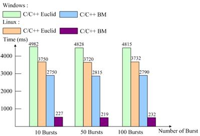
Figure 15 Execution time of different algorithms using C/C++ under different operating systems
The average execution time after running the full MPE-FEC mechanism on the Linux operating system is less than the execution time on Windows. In addition, the execution time of the BM algorithm on Linux and Windows is about 2.5 seconds, and it can meet the time requirement of real-time playback of the DVB-H receiver.
Finally, after Windows adds the test file to the error, the data obtained after error correction through the software system designed by the research institute is saved into a file and then played.
6 Conclusion
This study uses pure software to simulate the implementation of DVB-HMPE-FEC error correction mechanism, and can indeed fix the error added to the test file, although the data processing time on the Windows operating system has exceeded the real-time playback time requirement. However, the results of the RS decoding test using the BM algorithm on Linux have met the constraints of real-time playback. Therefore, in terms of system execution time and real-time playback, for future software design implementation, implementation on Linux may be more ideal than on Windows.
APM model SPS300VAC12000W 3 Phase Ac Power Supply system is ideal for every test scenario: like home electronic appliances, power adapters, LEDs, and even laboratory testing etc. This ac source system is single 3-phase output Programmable Ac Power Supply which provides with high power density.
Some features as below:
- 5.6`` large touch color screen, possess complete functions and easy to operate.
- Support for USB data import/export and screen snap from front panel.
- AC+DC mixed or independent output mode for voltage DC offset simulation.
- Capable of setting voltage and current output restriction, support for constant current output mode.
- Capable of setting output slope of voltage and frequency.
- Capable of setting ON/OFF phase angle.
- With reverse current protection to avoid current flowing backward.
- Built-in power meter, which is capable of measuring 5 electrical parameters per phase, including voltage, current, power, etc.
- Support mA current measurement function.
12000W Three Phase Ac Source System
12000W Three Phase Ac Source System,Uninterruptible Power Source,Three Phase Generator,3 Phase Power Converter
APM Technologies (Dongguan) Co., Ltd , https://www.apmpowersupply.com