introduction
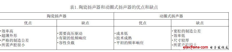
Today's portable devices require smaller, thinner, and more power-saving electronic components. For compact mobile phones, moving-coil speakers have become a limiting factor for manufacturers to produce ultra-thin phones. Driven by this demand, ceramic or piezoelectric speakers are rapidly emerging as alternatives to moving coil speakers. Ceramic speakers can provide extremely competitive sound pressure levels (SPL) in ultra-thin, compact packages, and have great potential to replace traditional moving coil speakers. The difference between moving coil speakers and ceramic speakers is shown in Table 1.
Amplifier circuits that drive ceramic speakers have different output drive requirements than traditional moving coil speakers. The structure of the ceramic speaker requires the amplifier to drive a large capacitive load and output more current at a higher frequency while maintaining a high output Voltage .
1. Characteristics of ceramic speakers
The production process of ceramic speakers is similar to multilayer ceramic capacitors. Compared with moving-coil speakers, this manufacturing technology allows speaker manufacturers to more strictly control the tolerance of speakers. Strict tolerance control is very important to weigh the choice of speakers, and also affects the repeatability of the audio characteristics of different production batches.
The equivalent impedance of the ceramic speaker at the driver amplifier end can be approximated as an RLC circuit mainly composed of a large capacitor (Figure 1). In the audio frequency range, ceramic speakers are usually capacitive. The capacitance characteristics of the speaker determine its impedance decreases with increasing frequency. Figure 2 shows the relationship between the impedance of a ceramic speaker and its frequency, similar to a 1μF capacitor. The impedance has a resonance point, at which point the loudspeaker has the highest sound production efficiency. The drop in the impedance curve around the 1kHz frequency indicates the resonant frequency of the speaker.
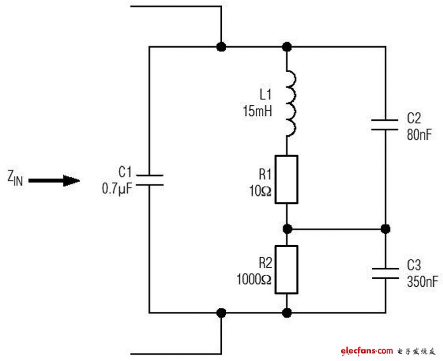
Figure 1 Ceramic speakers are mainly represented by a large capacitive load
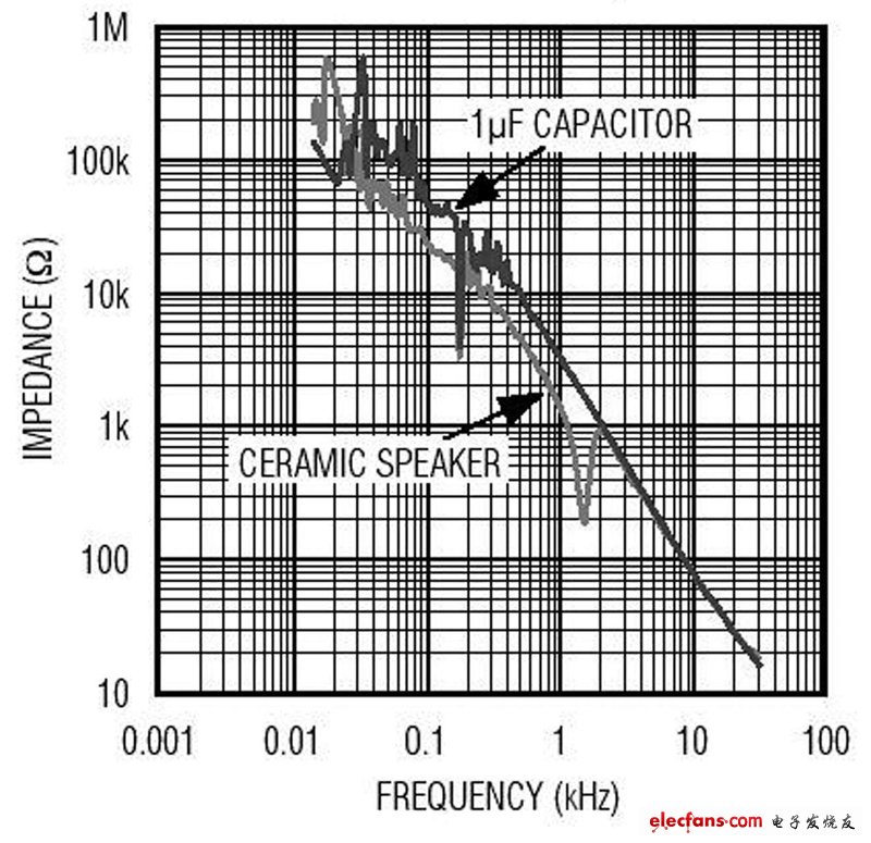
Figure 2 The relationship between ceramic speaker impedance and frequency, very similar to the 1μF capacitor
2. The relationship between sound pressure and frequency and amplitude
The AC voltage across the ceramic speaker causes the piezoelectric film in the speaker to deform and vibrate; the amount of displacement is proportional to the amplitude of the input signal. The vibration of the piezoelectric film causes the surrounding air to flow, thereby making sound. When the speaker voltage increases, the piezoelectric element deforms more and forms a larger sound pressure, which increases the volume.
Ceramic speaker manufacturers usually specify the maximum driving voltage of the speaker, a typical value of 15VP-P. The offset of the ceramic device reaches the limit when the voltage is maximum. When the applied voltage is greater than the rated voltage, the sound pressure will not increase, but the distortion of the output signal will be exacerbated. Figure 3 shows the relationship between the output sound pressure (SPL) and frequency of ceramic speakers when the voltage is at its maximum. When the voltage is greater than the rated voltage of the speaker, the distortion of the output signal increases.
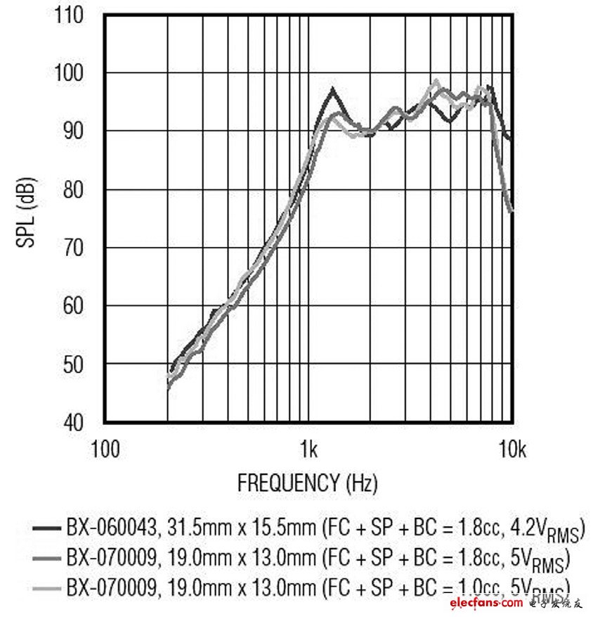
Figure 3 The relationship between the output sound pressure (SPL) of ceramic speakers and frequency
Test conditions: mono, positive launch, 10cm.
By comparing the graph of the relationship between SPL and frequency and the graph of the relationship between impedance and frequency, it can be clearly seen that when a piezoelectric speaker produces a high SPL, the efficiency is highest at the self-excited frequency.
3. The requirements for driving ceramic speakers to the amplifier
The ceramic speaker manufacturer specifies the maximum voltage, that is, the maximum sound pressure from 14VP-P to 15VP-P. In this way, the question becomes how to generate these voltages when powered by a single power supply. One solution is to increase the Battery Voltage to 5V with a switching regulator. With a 5V voltage, system designers can choose a single-supply amplifier with a bridge load (BTL). Bridging the load can produce a voltage doubling effect on the speaker. However, when a 5V single power supply is used to power a BTL amplifier, the output voltage has a theoretical 10VP-P swing. At this voltage, the ceramic speaker cannot output the highest SPL. In order to get a higher SPL, a higher power supply voltage must be used.
Another approach is to use a boost converter to adjust the battery voltage to 5V or higher. This solution also has its own problems-that is, the size of the required device. The size of the overall scheme can be judged according to the peak value of the inductor current. In order to ensure that the magnetic core will not be saturated, the size of the inductor must be large enough. Large current and small size inductors can also be found on the market. However, the core saturation current rating of this type of inductor may not be sufficient to meet the requirements, and it cannot provide the high voltage and large load current required to drive the speaker under high frequency conditions.
Driving ceramic components requires large currents while avoiding current limiting. This is because the impedance of the ceramic speaker is very low at high frequencies. The amplifier used to drive the ceramic speaker must have a sufficiently large drive current so that when a large amount of high-frequency components enter the speaker, the device will not enter the current limiting mode.
Figure 4 shows the application circuit of the MAX9788 Class G amplifier. Class G amplifiers have two supply voltages, high voltage and low voltage. When the output signal is small, the low voltage power supply is used; when the output signal requires a higher voltage swing, the high voltage is switched to the output stage for power supply. Because Class G amplifiers have low-voltage power supplies, when the output signal is small, the efficiency is higher than Class AB amplifiers. Due to the high-voltage power supply, Class G amplifiers can withstand transient peak voltages.
The MAX9788 in Figure 4 uses an on-chip charge pump to generate a negative supply voltage opposite to VDD. When the output signal requires high-voltage driving, the negative power supply voltage acts on the output stage. The device provides an optimized solution for driving ceramic speakers, which is more efficient than traditional solutions using class AB amplifiers and boost converters.
Loudspeaker manufacturers usually recommend a fixed resistor (RL) in series with ceramic speakers, as shown in Figure 4. When the signal contains a lot of high-frequency components, use this resistor to limit the current output of the amplifier. In some applications, if the frequency response bandwidth of the audio signal transmitted to the speaker is limited, this fixed resistor may not be used. For amplifiers, the use of resistors ensures that the speakers are not short-circuited.
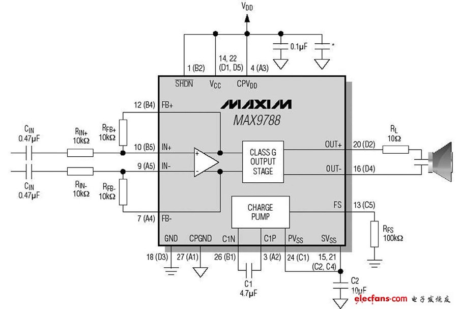
Figure 4 Typical ceramic speaker application circuit using MAX9788
The capacitance of existing ceramic speakers is about 1 μF. The impedance of the speaker in Figure 4 is 20Ω at 8kHz and 10Ω at 16kHz. In the future, ceramic speakers may have a larger capacitance, so that the amplifier can provide more current at the same frequency.
Electric vehicle batteries are designed to be more robust, as they carry a heavier load and last much longer. Of course, they`re also a little more expensive than your average Iphone Battery.
It`s no secret that batteries represent a large chunk of EV change, and are presumed to be one of the bigger stumbling blocks to EV ownership.
Of course, cell prices and battery pack prices are two different entities. A battery pack includes individual cells, supporting structure, a cell cooling system and a battery management system.
To understand what impacts a battery`s life, it`s important to first understand how it works. EV batteries are lithium based – when they are charged and discharged once, it`s called a cycle. A battery`s capacity will degrade as the cycle number increases. And battery life is measured in those cycles, with the industry standard of cycles close to 80 percent considered a benchmark.
EV Battery - Eectric Vehicle Batteries
24v 18650, 18650 48v, battery package, ebike bms
Shenzhen Powercom Electronics Co., Ltd. , https://www.expowercome.com