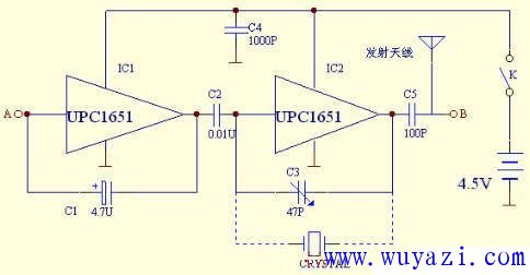
This schematic illustrates a multi-purpose signal generator built using the μPC1651 IC. The circuit consists of two main oscillators: IC1 along with C1 creates a low-frequency oscillator operating at approximately 400 Hz, while IC2 combined with C3 generates a high-frequency oscillator around 37 MHz. The low-frequency signal from C2 modulates the high-frequency signal, creating a composite output that can be used for various testing purposes.
The harmonics produced by the high-frequency oscillator are particularly useful for testing TV signals on different channels, displaying black and white stripes that help evaluate the performance of the television. The signals from points A and B serve as test sources for the low-frequency and video channels respectively. To improve frequency stability, you can replace C3 with a quartz crystal, as shown in the dashed line in the diagram.
If you prefer flexibility, you can use a small socket instead of C3 (ensuring minimal wiring length) and insert a crystal oscillator of varying frequencies. This allows you to create an intermediate frequency signal source for both recorders and TVs. Common crystal frequencies used for such applications include 465 kHz, 10.7 MHz, 6.5 MHz, 4.43 MHz, and 37 MHz. These values provide a good starting point for tuning and testing various devices.
 ---
Let me know if you'd like further modifications or a different style!
---
Let me know if you'd like further modifications or a different style!Tower Type Line Interactive UPS
Line Interactive UPS
Shenzhen Unitronic Power System Co., Ltd , https://www.unitronicpower.com