Read related series chapters
Detailed explanation of the key technology foundation of single chip microcomputer (1)
First, the role of the reset circuit of the CPU and the microcontroller and the basic reset mode
During the power-on or reset process, control the reset state of the CPU: keep the CPU in the reset state during this time, instead of working on a power-on or just reset, prevent the CPU from issuing incorrect commands, performing incorrect operations, or improving Electromagnetic compatibility.
Regardless of the type of microcontroller used by the user, the design of the microcontroller reset circuit is always involved. The design of the reset circuit of the single chip directly affects the reliability of the whole system. Many users have designed the MCU system, and after the successful debugging in the laboratory, there have been phenomena such as "dead" and "program flying" on the site. This is mainly caused by the unreliable design of the reset circuit of the MCU.
Basic reset method
The microcontroller needs to be reset at startup to keep the CPU and system components in a certain initial state and start working from the initial state. The reset signal of the 89 series MCU is input from the RST pin to the Schmitt trigger in the chip. When the system is in normal operation and the oscillator is stable, if there is a high level on the RST pin and is maintained for more than 2 machine cycles (24 oscillation cycles), the CPU can respond and reset the system. The reset mode of the single-chip system is: manual button reset and power-on reset.
1, manual button reset
Manual button reset requires manual addition of a high level to the reset input RST (Figure 1). The general method is to connect a button between the RST terminal and the positive power supply Vcc. When the button is pressed artificially, the +5V level of Vcc is directly added to the RST terminal. The manual button reset circuit is as shown. Since the human action is fast, the button remains on for tens of milliseconds, so the time requirement for resetting can be fully met.

figure 1
2, power on reset
The power-on reset circuit of the AT89C51 is shown in Figure 2. As long as a capacitor is connected to the Vcc terminal on the RST reset input pin, a resistor can be connected to the ground. For CMOS type MCUs, since there is a pull-down resistor inside the RST terminal, the external resistor can be removed and the external capacitor can be reduced to 1?F. The power-on reset process is when the power-on is reset, the reset circuit is applied to the RST terminal through a capacitor to a brief high-level signal. The high-level signal gradually falls back with the charging process of the capacitor by Vcc, that is, the high voltage of the RST terminal. The duration of the flat depends on the charging time of the capacitor. In order to ensure that the system can be reliably reset, the high level signal at the RST terminal must be maintained for a sufficient period of time. At power-on, the rise time of Vcc is about 10ms, and the start-up time of the oscillator depends on the oscillation frequency. For example, the crystal frequency is 10MHz, the start-up time is 1ms, the crystal frequency is 1MHz, and the start-up time is 10ms. In the reset circuit of Figure 2, when Vcc is powered down, the voltage at the RST terminal will inevitably fall below 0V quickly. However, due to the limitation of the internal circuit, this negative voltage will not damage the device. In addition, during reset, the port pins are in a random state. After reset, the system sets the port to the all "1" state. If the system does not receive a valid reset at power-on, the program counter PC will not get a suitable initial value, so the CPU may start executing the program from an undefined location.

figure 2
3, integral type power-on reset
A commonly used power-on or switch reset circuit is shown in Figure 3. After power-on, due to the charging of capacitor C3 and the action of the inverting gate, RST is held high for a period of time. When the MCU is already running, pressing the reset button K and releasing it can also make RST a high level for a period of time, thus realizing the operation of power-on or switch reset.
According to the actual operation experience, the capacitance and resistance reference values ​​of this reset circuit are given below.
In Figure 3: C: = 1uF, Rl = lk, R2 = 10k

Figure 3 integral power-on reset circuit
Second, the steps and difficulties in programming the microcontroller application
1 Introduction
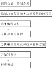
How to write a single-chip application, this is a very practical topic, but also a difficult and meticulous work. If you follow certain steps and find out the difficulties, you can get the results with half the effort with these difficulties. In the following, based on the experience in the actual work, I will talk about the few steps that must be taken in actual development and the difficulties that may be encountered. For a single-chip application, the compilation process is shown in Figure 1.
2 preparation steps
2.1 Find out the function and write the plan
After receiving a MCU project design file, it is not a matter of writing the program immediately. Instead, it carefully studies the technical requirements or technical descriptions put forward by the user. According to these technical requirements and technical descriptions, that is, the customer requirements, the main functions that the program should have are written. Clear, write carefully, this is the most critical job. If you are not sure, you should ask the customer and the user clearly. Otherwise, after the design is completed, some functions will be found to be troublesome because they have not been considered beforehand. It may be easy to add some functions that need to be re-added, and some may be due to It cannot be realized without prior consideration.
2.2 Write the general flow chart and the flow chart of each function module
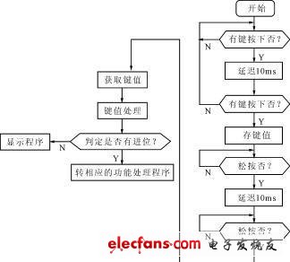
According to the program function to be completed, the total flow chart is written. According to the general flow chart, the whole program is divided into several main function modules. Each function module must write the basic flow chart, which is mainly for the later program writing. A guiding role. Of course, there will be some changes in the actual programming process, and a basic process will guide you in the process of writing the program without much deviation. For example, write a keyboard scan and distinguish whether it is a function key or a numeric key subroutine. If it is a function key, it will be transferred to the corresponding function processing program; if it is a numeric key, it will be displayed on the corresponding digital tube; you can write its flowchart. as shown in picture 2.
2.3 Prepare the information needed for programming
These materials are mainly books, magazines, etc. in programming languages. Because some information about the programming language can not be remembered clearly by any programmer, such as the meaning of each instruction, the hardware circuit involved in the operation of each instruction. If the information is prepared adequately, you can put it on the side of the case and check it if necessary.
2.4 Human Machine Interface Programming
The human-machine interface of the project realized by the single-chip microcomputer is relatively simple. If it is LED display, it should be based on the number of LEDs to select a simple, clear, user-looking prompt; the number of data displayed should fully consider the technical requirements of the user.
2.5 Analysis of programming difficulties and technical solutions
Even a skilled programmer will encounter some difficulties during the programming process. In order to complete the program design smoothly, the framework of the whole program should be analyzed according to the functions and program flow completed by the program, and the difficulties of the whole program should be located according to the skills mastered by the program, and then the best algorithm can be found. For example, for a slightly larger project, the programming of the keyboard scan and display should be a difficult point in microcontroller programming.
(1) Both the keyboard scan and the display process are closely related to the hardware part.
When the chip selection signal is selected, the keyboard must be clear whether the MCU chip is high-level strobe or low-level strobe; after strobing the keyboard, the state of the keyboard needs to be read back. Anti-shake processing is also performed on the read-back keyboard state; if the keyboard is shaken, the read-back data is discarded, and the keyboard state is re-read; if it is determined that the keyboard is pressed, the key value can be processed; the processed key value is sent to display or Used as other. It can be seen that each of the above processes deals with the hardware circuit.
(2) The algorithm involved in keyboard scanning and display is more complicated
Because the process of scanning the keyboard is to traverse each button, identify the jitter, identify whether the button is released, etc.; in addition to delay the appropriate time to read the key value again. The display process also traverses each digital tube or liquid crystal character; in the process of looking up the table, the display process uses a more complicated loop traversal algorithm.
(3) The distinction between numeric keys and function keys
It is the number key to send the display, the function key is transferred to the corresponding function subroutine, and the combination of the two constitutes a more complicated scatter program. The MCS51 MCU has a ready-made loose rotor program for reference. The PIC can be applied with reference to the MCS51's loose rotor program.
The above three points are the difficult part of MCU programming, and should be found out carefully before programming. Through analysis, all the possible difficulties are found out and the corresponding algorithms are found out, which is correspondingly smooth in the process of writing later.
2.6 writing program
After the above preparations are completed, you can start writing the program. Because there is a clear program flow, with sufficient information, the difficulties that may be encountered basically find a solution; thus, the preparation is sufficient in advance, even if it is difficult to solve in the later process of writing, it is easier to solve . This saves a lot of time, so that you can calm down and carefully write programs according to the program and process. In addition, generally write a function program to debug, after writing another function code, this can prevent the mutual influence of debugging after all the code is written, so that you can figure out which part of the program has problem.
2.7 program debugging
The debugging process of the program is a relatively complicated process, and some require a high degree of skill and certain methods. General programming software provides basic methods such as single-step, single-step crossing, breakpoint, and running to the cursor. Generally, mastering these basic methods can solve most problems. After a long period of debugging practice, you can naturally master certain debugging skills, that is, practice makes perfect.
3 Conclusion
The above is the 7 major steps that must be passed to program a general-purpose microcontroller program. If the work of these seven processes is done adequately, it will be able to write a satisfactory single-chip program.
App Control Window Cleaning Robot
China Window Washing Robot , Glass Cleaning Robot ,Automatic Window Cleaner Robot,App Control Window Cleaning Robot, we offered that you can trust. Welcome to do business with us.China window clean robot manufacture and big supplier, best quality and good price.
2019 APP Window Clean Robot ,smart clean robot. Window Cleaning Robot Video welcome to see our youtube.

if you have any require window cleaning robot wireless,please let me know,thanks
App Control Window Cleaning Robot
Window Washing Robot,Glass Cleaning Robot,Automatic Window Cleaner Robot,App Control Window Cleaning Robot,Window Cleaning Robot Video
Zhengzhou Bangmi Smart Technology Co., Ltd. , https://www.globalcleanrobot.com