The mechanism of audio system noise formation is more complicated, and the main reasons and solutions for system noise are particularly important.
In the process of recording sound reinforcement or audio transmission, noise is a ripple voltage with a certain frequency that enters the power supply circuit of the audio equipment through the power line, which is generally present and is very headache and difficult to solve. Generally, the more devices that make up audio equipment or the longer the signal transmission distance, the greater the noise of the system; it even makes the audio system unable to perform normal recording or sound reinforcement work.
The main cause of noise
Electromagnetic radiation interference noise
Stray electromagnetic radiation interference of the environment, such as high-frequency electromagnetic wave radiation interference of communication equipment such as mobile phones and walkie-talkies, electric pulse radiation of elevators, air conditioners, car ignition, welding, etc. Radiation of silicon controlled rectifier control equipment for studio lighting control will pass The transmission line is directly mixed into the transmission signal to form noise or pass through the poorly shielded equipment casing to interfere with the internal circuit of the machine (practice shows that in some special occasions, such as studios that use a large number of thyristor dimming equipment, if not reliable The shielding and grounding measures, the noise will be very serious).
Power supply noise
In addition to electromagnetic radiation, the introduction of interference noise in the power supply is also the main reason for the noise (the urban power grid forms a very serious source of interference due to the joint access of various lighting equipment, power equipment, and control equipment (such as those connected to the same power grid Light control equipment, air conditioners, motors and other equipment will produce spikes, inrush currents, and ripple voltages of different frequencies on the power line. When the power supply line of the audio equipment passes through the power line, there will always be some interference noise voltage that cannot pass The effective filtering of the power circuit of audio equipment will inevitably form noise inside the equipment (especially the high-power equipment that does not meet the required electromagnetic compatibility performance in the same power grid is the main reason for interference with audio equipment).
Ground loop noise
In an audio system, the entire system must be well grounded, and the grounding resistance must be 4 ohms. Otherwise, the induced charge generated by the equipment in the audio system due to various radiation and electromagnetic induction will not be able to flow into the ground, thereby forming a noise voltage superimposed on the audio signal.
When there is a ground potential difference between the ground wires of different devices due to the difference in ground resistance, or when there is a loop in the internal ground of the system, it will cause ground noise. When two different audio systems are interconnected, noise may also occur The noise is caused by the direct connection of the ground lines of the two systems.
Circuit noise inside the device
Due to the electrical noise generated by the internal electronic components working alone in a device, the required specifications can be achieved. However, when multiple devices are connected in series, the noise will accumulate and increase. In practical applications, some low-grade equipment will increase the hum of the equipment itself due to poor internal power supply filtering, and sometimes form very serious noise in the system.
Ways to eliminate noise
Correct connection of the system
In an audio system, there are usually many connected devices. Different devices have different interface forms, and different connectors are used. There are balanced and unbalanced input and output forms. In order to effectively shield the external electromagnetic radiation interference, shielded cables must be used uniformly and connected in a correct way.
As we all know, when the audio signal transmission adopts the balanced transmission mode, the common mode interference level generated by the external interference source on each of the two signal lines in the cable is almost equal to the ground loop. At the input of the internal amplifier of the device, the common-mode voltage on the two signal lines will be replaced by a differential-mode voltage to cancel each other out, forming an interference voltage. Therefore, balanced connection methods should be used whenever possible.
When connecting with an unbalanced output device, you can directly use a single-core shielded cable to connect the port of the balanced device to the port of the unbalanced device. Instead of using a balun. The noise induced by the shielding layer is mixed into the audio signal, thereby increasing the noise. This will be a major way to introduce noise. The recommended method is to use a double-core shielded cable regardless of balanced or unbalanced transmission, and the shielding layer is only grounded at one end of the balanced output or input, as shown in Figure 1. When both ends are unbalanced connections, if the transmission distance is far, it is best to use a balanced-unbalanced converter or audio isolation transformer to convert to balanced transmission, as shown in Figure 2. The connection of current audio equipment generally uses voltage jumper connection. That is, the line output of all audio equipment is a low-impedance output, and the line input of the load uses a high-impedance input. Except for the connection between the power amplifier and the speaker, there is generally no need to specifically consider impedance matching.
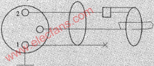
Figure 1 Balanced and unbalanced connections
Figure 2 Unbalanced conversion to balanced transmission with good grounding
In order to make the shielded cable shield the external stray electromagnetic interference. The shielding layer must have correct connection and good grounding. In practice, all equipment is suspended, which is the most commonly used measure without special ground conditions.
But this is a very unstable working state, which often produces unstable random noise, so the whole system should be well grounded. First of all, there should be a dedicated ground wire, and the ground resistance is less than 4 ohms. The zero line of the power supply cannot be used as the ground wire of the audio system equipment. In outdoor places, you can consider burying temporary ground wires. The simplest method is to insert a one-meter-long steel pipe or aluminum alloy pipe into the ground and do salt intrusion treatment. The effect is very good.
The general system is a link system with multiple devices connected by cables. It is easy to form a chain grounding method by its shielding system. When electromagnetic radiation or electrostatic induction noise is generated on a certain device, the entire system will generate an induced voltage due to the grounding system formed by the shielding layer of the transmission line and the iron device shell. In turn, the system generates a certain level of noise. This type of interference is especially noticeable in audio systems with long links. Therefore, the system should avoid using the chain grounding method as much as possible, and should use the star grounding method. That is, each device is connected to a unified ground point through a special ground wire, which requires that the shielding layer of the audio cable connecting all devices be grounded at one end. The ground wire of each device connected to the shielding layer is connected by a ground point of a special wire, as shown in Figure 3.
Figure 3 Device star grounding method
If the shielding layers at both ends of the signal transmission line are grounded, a ground loop must be formed. When the loop is interfered by electromagnetic radiation from other equipment, an induced current will inevitably appear in the shielding layer of the cable, resulting in serious interference noise and ground loop noise interference, as shown in Figure 4.
Figure 4 Schematic diagram of ground loop formation
In order to ensure that the system does not have a ground loop structure, it is required that only one grounding conductor can be interconnected between the devices, in occasions where the requirements are not strict. You can let unbalanced equipment levitate and share the ground wire of the next level equipment through the audio signal line. That is, the chain-shaped grounding is used, but the number of such chain-shaped groundings cannot be too many, generally not more than 2 levels. Otherwise, the noise will increase seriously.
The connection problem between the chassis should also be paid attention to. For example, many devices are installed on the same rack. If each device is connected to the ground separately, the 2 devices are connected to the chassis because they are installed on the same rack. Ground loop.
System isolation
In some large-scale audio systems, it is often composed of subsystems centered on multiple mixers, or interconnected with video equipment systems. Sometimes it is necessary to transmit signals to the far-end audio and video system, and radio stations and even commonly used telephone lines transmit audio broadcast live signals. For these long-distance connections, because different subsystems have their own independent grounding systems, once each subsystem is connected to the ground, it will inevitably form ground noise, as shown in Figure 5; on the other hand, due to the long transmission distance, the transmission line The grounding resistance of the shielding layer will increase, and even using unshielded transmission lines, etc., it is easy to introduce a large amount of external electromagnetic field radiation interference noise. In practical applications, if each system works independently, the noise can be controlled within the allowable level through reasonable wiring and grounding, but when multiple subsystems are interconnected, single-ended shielded grounding or long-line segment grounding is used There is no way to solve the radiated interference noise caused by long-distance transmission. Especially when using a huge telephone network for transmission, the best measure at this time is to use isolation. Install audio isolation transformers between multiple systems to isolate them from each other. The ground wires of multiple subsystems must not be connected, and optical isolation is used to completely isolate different subsystems, as shown in Figure 6, which has a good effect.
Figure 5 Isolation processing between systems
Figure 6 Optical isolation method consisting of 2 MD recorders Power purification
In order to isolate the interference noise formed by the public power grid, it is best or common to use an isolated and purified power supply or an isolated transformer. The grounding terminal of the isolated transformer or the purified power supply must ensure a reliable and good grounding. Otherwise, the effect of isolation is not good. It must be isolated from some high-power electrical appliances with strong interference, supply power separately, or install a filter at the power input of the audio equipment to filter out the interference noise.
Sometimes it is also possible to find a connection method that minimizes noise by changing the position of the live and neutral input of a single-phase powered audio device. This can also reduce some noise interference. It should also be noted that the audio transmission line must not be routed parallel to the power line. Cross-wiring the audio line and the power line can also reduce AC noise interference.
Conclusion
This article mainly discusses the problem of external interference noise in the practical application of audio and sound reinforcement equipment. Of course, some noise is thermal noise generated by the circuit inside the device. Some are the environmental noise in the scene directly contained in the input signal source or picked up by the microphone.
Small Machine Room Passenger Elevator
Circular Elevator,Machine Roomless Elevator,Small Machine Room Elevator,Small Machine Room Passenger Elevator
XI'AN TYPICAL ELEVATOR CO., LTD , https://www.chinaxiantypical.com