In this paper, for 65 & TImes; 65mm, there are nine 1 & TImes; 1mm, 1W LED chips on the other side, and the aluminum fins on the other side are ribs. The numerical method is used to solve the three-dimensional steady-state thermal conduction differential equation. The computer-specific software is used to calculate different LED chips. During the distribution, the temperature distribution on the surface of the heat sink chip is used to analyze the influence of the LED chip distribution on its heat dissipation according to its temperature field. The result is: Nine chips are concentrated to have the worst heat dissipation effect. The distance between the chips should be more than 5mm, and the chip temperature can be reduced by more than 5 ° C.
LED lighting is considered to be the next generation of lighting technology due to its significant energy saving. LEDs are cold light sources, and the infrared part is not included in their spectrums. At present, LED luminous efficiency only reaches 20%, which means that more than 80% of the electrical energy is converted into thermal energy. If the heat cannot be dissipated effectively, the temperature of the chip will rise, which will lead to a decline in light efficiency, increased light decay, and burn the chip in severe cases. LED chip heat dissipation is a major unsolved problem in the current development of LED lighting.
The heat dissipation process of the LED chip is not complicated. It is just a series of heat conduction processes plus convection heat exchange process. The temperature range is not high, which belongs to room temperature heat transfer. The heat conduction process in it can be solved by using computer-specific software to solve the three-dimensional heat conduction differential equation. Analyze the heat conduction process in the LED chip and the heat sink, and the convection heat transfer on the surface of the heat sink, analyze where the main thermal resistance is in the entire heat transfer process, what causes it, and you can get a very clear solution. Make people targeted.
However, the current LED heat dissipation and the heat dissipation of similar semiconductor chips lack this basic and guiding research. Even if some people do it, it is not known to everyone. As a result, today's LED heat dissipation technology is like the Spring and Autumn Period and the Warring States Period. The use of heat pipes has appeared, and even the use of loop heat pipes has been proposed. This article only studies and analyzes its impact on heat dissipation from the different distribution of LED chips, which will have a guiding significance for the design and manufacture of LED chips.
1. Model for calculation and simulation
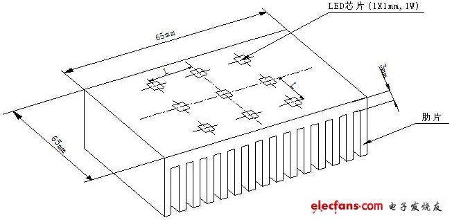
figure 1
As shown in Figure 1, there are nine 1 & TImes; 1mm, 1w chips on one side of the aluminum heat sink, as well as an insulating and thermal conductive layer with a 0.1mm thick thermal conductivity coefficient of 4w / (m · k), and the total area of ​​the fins Is m2, the air convection heat transfer coefficient is = 6 w / (m2 · k), and the thermal conductivity of aluminum is 202 w / (m · k). In order to simplify the calculation, without considering the heat conduction problem in the fins, the fin heat dissipation surface is simplified and converted into 65 & TImes; 65mm, and the convection heat transfer coefficient is 85 w / (m2 · k). That is to say, one side is a convection heat exchange surface (= 85w / (m2 · k)), and the other side is an aluminum block (65 × 65 × 3mm) with 9 chips (1 × 1mm, 1w) when the chip spacing is different Its internal temperature field.
#p 结果 # e #
Solve the equation:
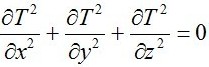
It is the three-dimensional steady-state heat conduction differential equation, usually called the Laplace equation. Use special calculation software to solve.
2. Calculation result
Figure 2 shows the temperature distribution across the center point of the metal surface of the heat sink where the LED chip is located at different chip pitches.
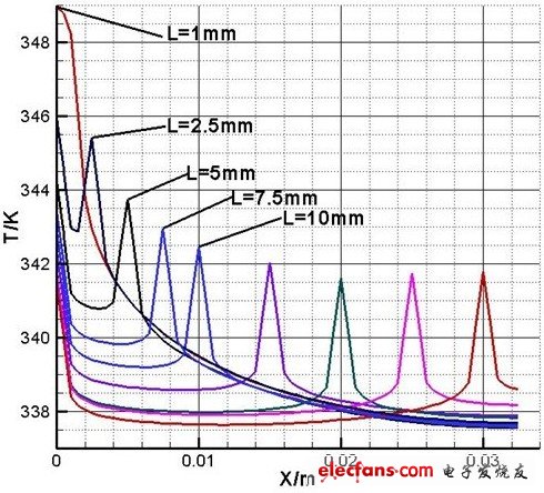
The chip pitch L is 1mm, 2.5mm, 5mm, 7.5mm, 10mm, 15mm, 20mm, 25mm, 30mm.
When L = 1mm, that is, 9 LED chips are gathered together without gaps.
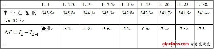
Table 1 lists the temperature values ​​and differences of the center point (that is, the highest temperature point) of the metal surface of the heat sink where the LED chip is located. In the above calculation, the ambient temperature is 40 ° C (313K).
3. Analysis
It can be clearly seen from Figure 2 and Table 1: When 9 LED chips are grouped together (chip spacing L = 1mm), the center point (the highest temperature point where the chip is located) has the highest temperature, that is, the heat dissipation effect is the worst . When the chip pitch increases by 1.5mm (L = 2.5mm), the maximum point temperature drops by 3.1 ℃, and when the chip pitch increases by 4mm (L = 5mm), the maximum point temperature drops by 4.8 ℃. When the chip pitch is L = 7.5mm, the highest point temperature drops by 5.6 ℃. When the chip pitch L = 10mm, the temperature drops by 6.1 ℃. When the chip pitch L = 20mm, the temperature drops by 7.2 ℃. The temperature drops significantly within the distance L = 10mm.
4. Results
(1) The distribution of LED chips has a great influence on heat dissipation, and LED chips should be dispersed.
(2) For 1 × 1mm, 1w LED chips, the chip spacing is preferably 5 ~ 10mm.
HDMI Adapter Cable,A Hdmi Antenna,Phone HDMI Cable Phone to TV,HDMI Cable
Dongguan City Leya Electronic Technology Co. Ltd , https://www.dgleya.com