Summary: Looking at the constantly dithering waveform on the display, the headache is so powerful, why is the waveform always shaking? Where is the problem?

We often see various trigger modes in the trigger options of the oscilloscope. After setting the trigger mode, the waveform still cannot be displayed stably. Is the oscilloscope unable to meet the test requirements or the settings are incorrect? How to set the waveform to display stably?
Triggered concept
Triggering is one of the biggest features that distinguishes a digital oscilloscope from an analog oscilloscope Triggering is to synchronize the oscilloscope's scan with the observed signal to display a stable waveform. In order to meet different observation needs, different "trigger modes" are required, and there are mainly three trigger modes:
1. Automatic triggering : waveform display is displayed regardless of whether the trigger condition is met, and the trigger position is random. At this time, the waveform “jitter†is presented, which is suitable for low repetition rate and unknown signal level;
2. Normal trigger : display the waveform only when the trigger condition is met. When the trigger condition is not met, keep the original waveform display and wait for the next trigger. This mode is suitable for low repetition rate signals and signals that do not require automatic triggering;
3. Single trigger : In the single trigger mode, the oscilloscope is always in the waiting state until a waveform that meets the trigger condition occurs, and a trigger is performed, and then the waveform sampling is stopped.
As shown in the figure below, from the automatic trigger to the normal trigger, after the corresponding trigger condition is set, the waveform changes from jitter to smooth.
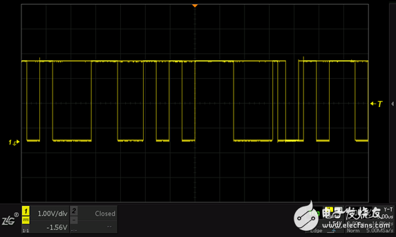
Figure 1 automatic trigger and normal trigger
2. The role of triggering
There are two main functions of triggering: 1. Isolate the signal of interest; 2. Synchronize the waveform (stable display waveform).
In order to understand the trigger more vividly, you can use a very acidic word to describe: the so-called trigger is "stop at this moment", and can be understood as "waiting for the moment." The trigger circuit can be a person with a pair of innocent eyes watching in front of everyone (signal flow), when seeing the person in the middle (trigger condition), the eyes will stare at the person, let the person stay in her position (trigger point). But she will continue to look for her next person, every time she finds the person who is interested, she will let the person in the place stay at the position (trigger point) where she is watching. Therefore, the position of her eye gaze point (trigger point) is only for those who are interested (waveforms that satisfy the condition).
As shown in the figure below, after setting the under-trigger trigger and normal trigger, the runt pulse signal is triggered and displayed stably on the screen.
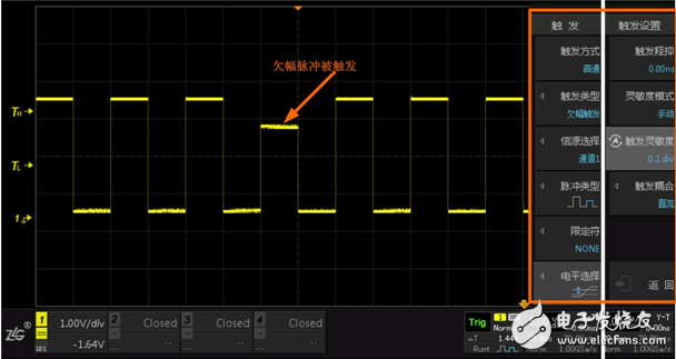
Figure 2 Runt pulse is triggered
3. How to set the trigger condition
In actual use, the choice of different trigger modes should be judged according to the characteristics of the observed signal and the content to be observed. There is no fixed rule, and it is often an interactive process. By selecting different trigger modes to understand the characteristics of the signal, Select the effective trigger mode for the characteristics of the signal and what you want to observe. The most important thing in this process is to understand the working mechanism of different trigger modes, to understand the characteristics of the observed signals and to clarify what is to be observed.
1. Unknown signal: When the signal to be measured is not specially understood, automatic triggering should be used. At this time, at least one thing can be seen on the screen. Even if only the scanning line can be seen, the vertical gain and vertical position can be adjusted. The parameter “found†the waveform such as the time base rate, and then stabilize the waveform by selecting the trigger source, trigger edge, trigger level, and so on.
2. Known signal: When the measured signal is a known type signal, the corresponding trigger condition can be selected in the trigger setting. At this time, the measured signal can be displayed on the screen. If the measured signal has “jitter†condition The waveform can be stably displayed on the screen by adjusting the position of the automatic, normal trigger type and trigger level.
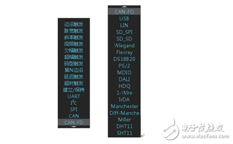
Figure 3 trigger mode
4. Template trigger
After trying to set various trigger conditions, if you still can't capture the desired signal, you can use the template trigger of ZDS2000 series oscilloscope. The working principle is: the template will continuously monitor whether the waveform touches the template area. The signals passing through the template can be isolated and captured. However, the template trigger function needs to be equipped with a high waveform refresh rate to achieve effective implementation. The template trigger completes the trigger function, greatly improving the ability to capture abnormal signals. When the various trigger conditions are still not found, the template trigger function is not found. It will be a big boost!
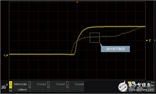
Figure 4 template trigger
By setting the trigger mode reasonably, we can help us to observe the waveform quickly and stably. The ZDS2024PLUS has a waveform refresh rate of 330,000 times/second. It is equipped with 11 basic triggers, 22 protocol triggers, and innovative template triggers.
This Tool Box series including all Metal Tool Box which are widely use on trailer, UAE, truck, garage., etc, it can be produced with aluminum, iron steel or stainless and can produce it according customers' diagram or special requirement.
Tool Box
Tool Box,Moveable Tool Box,Mobile Storage Tool Box,Portable Metal Tool Box
Foshan Dinghan Electrical Technology Co., Ltd , https://www.dinghanelectrical.com