SPI is a high-speed, full-duplex, synchronous communication bus that occupies only four wires on the pins of the chip, saving the pins of the chip and saving space for the layout of the PCB. Because of this simple and easy to use feature, more and more chips are now integrating this communication protocol. SPI is a ring bus structure, composed of ss (cs), sck, sdi, sdo, the timing is actually very simple, mainly under the control of sck, two bidirectional shift registers for data exchange.
The SPI bus is a three-wire synchronous interface introduced by Motorola. It communicates synchronously in 3-wire mode: one clock line SCK, one data input line MOSI, and one data output line MISO; it is used for full duplex of CPU and various peripheral devices. Synchronous serial communication. The main features of SPI are: it can send and receive serial data at the same time; it can be used as master or slave; provide frequency programmable clock; send end interrupt flag; write conflict protection; bus competition protection.
The SPI bus has four modes of operation (SP0, SP1, SP2, SP3), the most widely used of which are SPI0 and SPI3. In order to exchange data with peripherals, the SPI module can configure the output serial synchronous clock polarity and phase according to the peripheral operation requirements. The clock polarity (CPOL) has no significant impact on the transmission protocol. If CPOL=0, the idle state of the serial synchronous clock is low; if CPOL=1, the idle state of the serial synchronous clock is high. The Clock Phase (CPHA) can be configured to select one of two different transmission protocols for data transmission. If CPHA=0, the data is sampled on the first edge of the serial synchronous clock (rising or falling); if CPHA=1, the data on the second edge of the serial synchronous clock (rising or falling) is sampling.
The phase and polarity of the SPI master module and the peripheral audio clocks it communicates with should be the same.
Detailed SPI Timing---The SPI Interface Outputs the First Data at Mode 0 The SPI interface has four different data transmission timings, depending on the combination of CPOL and CPHL. The four timings are shown in Figure 1. The relationship between timing and CPOL and CPHL can also be seen from the figure.
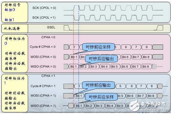
figure 1
CPOL is used to determine the level when the SCK clock signal is idle. CPOL=0, the idle level is low, and when CPOL=1, the idle level is high. CPHA is used to determine the sampling instant, CPHA = 0, sampled on the first clock edge of each cycle, CPHA = 1, sampled on the second clock edge of each cycle. Since the device I am using operates at mode 0 (CPOL = 0, CPHA = 0), Figure 1 is simplified to Figure 2, focusing only on the timing of mode 0.
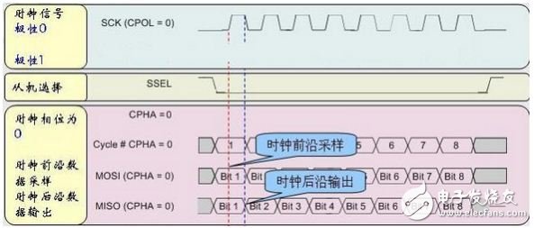
figure 2
Let's focus on the first clock cycle of SCK, sampling the data on the leading edge of the clock (rising edge, the first clock edge), and outputting data on the trailing edge of the clock (falling edge, second clock edge). First look at the master device, the data bit1 of the output of the master device (MOSI) is sampled by the slave device at the leading edge of the clock. When does the master device output bit1? The output time of bit1 is actually half a clock cycle before the rising edge of SCK before the SCK signal is asserted. The output timing of bit1 has no relationship with the SSEL signal. Looking at the slave device, the input port MISO of the master device also samples the bit 1 of the slave output at the leading edge of the clock, and at what time does the slave device output bit1? The slave device outputs bit1 immediately after the SSEL signal is asserted, although the SCK signal has not yet taken effect.
From this picture, it can be clearly seen how the bit 1 of the master-slave device is output.
Wire Feeding Hose is a very important part in the spraying.
Wire Feeding Hose
Wire Feeding Hose,Wire Cement Feeding Hose,Feeding Concrete Hose,Wire Reinforced Hose
Shaoxing Tianlong Tin Materials Co.,Ltd. , https://www.tianlongspray.com