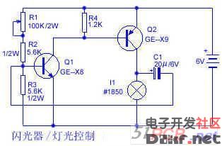
The circuit is a two-stage direct-coupled transistor amplifier that is connected to a self-excited multivibrator. Adjusting the potentiometer R1 can change the length of the flash time and change the interval between the flashes.
Wonderful use of LM317 flashing lights
The LM317 is often used as an adjustment component in voltage regulators. Here is an unusual application. A small 12V bulb can be illuminated by a small number of external components.
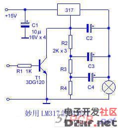
As shown in the figure, using the given component parameter values ​​and signals, when the circuit is turned on, the small bulb will flash at 4 Hz. Of course, if the component parameters (R2 or C2, R2 or C2 are changed, other corresponding resistors) Or the capacitance value is changed to be the same as R2 or C2), the frequency of flashing will also change. To make the flashing light stop flashing, drive T1 with a voltage of >1V.
Since the LM317 itself transmits a current of >1A, the circuit can automatically limit the turn-on current, so the life of the bulb is quite long. Those who are interested may wish to try.
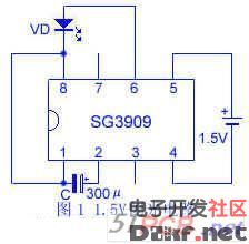
Multi-purpose flash circuit
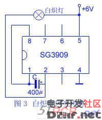
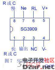
The SG3909 is an integrated component of the LM3909. It can be used interchangeably with the LM3909. The operating voltage can be less than 1.5V. The timing capacitor is used to boost the voltage and the 2V pulse is sent to the LED.
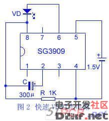
The pin row of the SG3909 is shown in Figure 7. The features of the SG3909 are:
1, micro power consumption work, a large flashlight battery can work for more than one year;
2, the power supply voltage is low, from 1V to 5V;
3, the drive current is large, as an oscillator can directly drive 8Ω speakers;
4, there are few external components, the circuit is self-starting, only need to add a battery and a capacitor to form a flasher;
5. Low cost and good brightness.
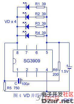
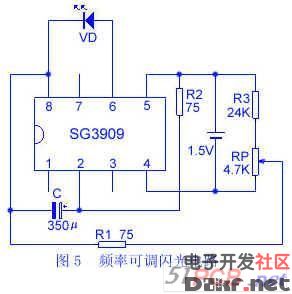
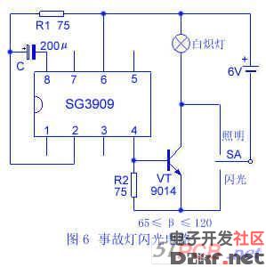
1 to 6 show various light emitting diodes VD and incandescent H flasher circuits of the SG3909. The flash frequency can be adjusted by adjusting the external resistor and capacitor.
Component selection: LED VD can be selected as follows: BT104 (yellow), BT304 (green), BT305 (red), other LED models can be used as long as the working voltage is 1.5V ~ 2.5V. The switch SA is KNX (1 × 2). The illumination lamp H is 6.3V, 0.1A (thread) or 6.3V, 0.15A (socket). The power supply GB uses 4F22-DC6V laminated battery, and can also be used to rectify DC 6V power supply, which is more economical. Other component parameters are marked as shown in Figures 1 to 6, and there are no special requirements.
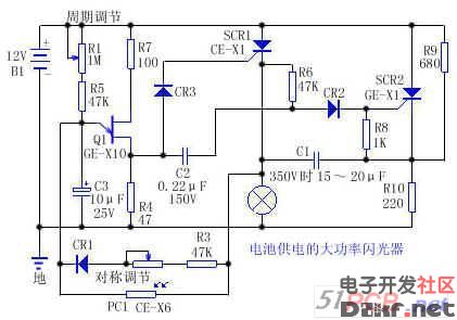
Battery powered high power flasher
This flasher is powered by a 12V car or vapor boat battery. It provides 36 to 40W output and variable flash frequency (up to 60 times / min), and can achieve independent on-off cycle control and photoelectric day and night control, so that the flasher automatically powers up at night and power off during the day. SCR1 and SCR2 form a basic DC flip-flop. The lamp load is connected to the cathode lead of a silicon controlled rectifier (SCR) so that the other end of the lamp can be at ground (negative) potential (which is desirable in some applications). The timing of the contacts is controlled by a conventional single-junction transistor oscillator circuit (Q1, R1, C3, etc.). Potentiometer R2 and diode CR1 can individually control the on/off timing. The photoresistor cuts off the single junction transistor start-up circuit during the day. The flash bulb is 12V, 3A.
Industrial computers and commercial computers have always been inextricably linked. They each have their own application areas, but they affect each other and promote each other, reflecting the progress of science and technology. At present, it is better to do Sanqi Tuoda in China and Advantech in Taiwan. Advantech has a higher reputation, but its price is higher. The industrial computer site can be embedded in the machine, cabinet or placed on the operation table, and it can be used as a man-machine display interface. It is used in telecommunications, electric power, multimedia, national defense, automation equipment, manufacturing and other fields. It is used as a man-machine interface, thin client, PLC and POS communication and control terminals. Digital hospitals are used as bedside service terminals and outpatient terminals to improve hospital service and management. Banks, shopping malls, hotels, railway stations, buses, subway stations, parks and other public places as media (advertisement) players or inquiry terminals. High-end residential quarters are used as home service terminals to implement intercom, message, cost inquiry, product order, home appliance management, temperature and humidity control, etc.
industrial pc,industrial computer,industrial touch computer,industrial computer waterproof,Fanless Industrial Computer,Panel Mount Computer
Shenzhen Hengstar Technology Co., Ltd. , https://www.angeltondal.com