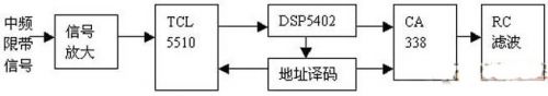
1 Introduction Based on the discussion of the basic band-pass sampling theorem, this paper analyzes the spectrum shifting characteristics of the under-sampling rate on the band-pass signal sampling, and combines the sampling, filtering and processing of the ordinary AM AM receiver IF signal to obtain the baseband. voice signal. This technique of signal processing with software helps to understand the theory of band-pass sampling filtering and provides theoretical and practical basis for software radio to receive data signals. The basic block diagram of the IF narrowband sampling implementation discussed in this paper is shown in Figure 1.

The front part of the signal acquisition can be a normal AM receiver, the input signal is fx, and the intermediate frequency signal fi=fl-fx output through the mixing, where fi=465 kHz is determined, and the signal bandwidth is 10 kHz. The sampling frequency of the AD conversion is fs=60 kHz, and the narrowband intermediate frequency signal is directly collected, and after being processed by the DSP, the voice signal is output through the DA. This work process uses the bandpass sampling theory.
2 Bandpass sampling theory and DSP hardware circuit
2.1 Bandpass sampling theory
The bandpass sampling theorem is a further extension of the Nyquist sampling theorem. The basic meaning of the Nyquist sampling theorem is: a frequency band-limited signal x(t) whose band is limited to (0, fh). If the sampling frequency of fs>=2fh is used to equally sample x(t), the obtained is obtained. The discrete signal x(n)=x(nTs), then the x(t) signal will be determined by the obtained sampled value x(n), and the sampled signal spectrum will not be aliased, so the original can be restored with a filter. The band limited signal x(t), which is a baseband signal near the zero frequency. The actual received radio signal is mostly a band-limited signal with a center frequency, and the ratio of the signal bandwidth to the center frequency is much less than 1 (B/fo<<1), that is, the center frequency fo is much higher than The spectrum width carried by the signal is known according to the basic sampling theorem. At this time, the sampling frequency fs>2fo, which not only requires a high-performance AD ​​converter, but also high-speed sampling data greatly aggravates the signal processing burden of the DSP. In order to allow the DSP enough time to process real-time signals, there are two main methods: (1) directly reduce the sampling rate; (2) perform high-speed sampling, and then use the extraction method to reduce the sampling rate. This article uses a method to directly reduce the sampling rate. So, does reducing the sampling rate cause problems such as signal aliasing? This is answered by the bandpass sampling theory.
Bandpass sampling theorem: Set a frequency band-limited signal x(t) whose band is limited to (fL, fH) if the sampling frequency fs satisfies: where n is the value that satisfies fs ≥ 2B (B = fH - fL) The largest integer value (0, 1, 2, ...), at this time x(nTs) with equal intervals sampling with fs can accurately determine the original signal x(t). And determine the center frequency of the bandpass signal, then. This expression indicates that when the sampling frequency is determined, there are many frequencies (or bandpass signals) that can produce the same frequency (or the same bandpass signal) under the condition that the value of n is taken by the above expression; Fo determines fs by choosing a different n. as shown in picture 2.
Where fs is the sampling frequency. When the frequency of the sampled signal fo is 3fs/4 and 5fs/4, the condition of fs>2fh is not satisfied, which is the undersampling condition. A signal fs/4 of the same frequency is output after undersampling, as indicated by the bold black line. Further, if the sampled signal is a band-limited signal with fo as the center frequency, the bandwidth is B, and the sampling frequency fs>2B, then the undersampling will output a sampling frequency fs/4 as the low center frequency. Limited band signal. Of course, sampling does not allow other signals to be mixed into the sampled signal, that is, it must be a band-limited signal. Otherwise, other signals satisfying the above formula will enter the frequency band. Secondly, according to the natural sampling theorem, the output spectrum will also have fs. The frequency-dependent spectral component, ie the output signal spectrum Xs, is:
This requires a DSP to design the filter to recover the original signal x(t). Cn is the coefficient of the Fourier series of the sampled pulses. According to the parameters introduced above, the IF signal of a conventional AM receiver with a sampling frequency of 60 kHz (8 bits) and a sampled signal of 465 kHz is a band-limited signal, and the signal bandwidth is B = 10 kHz.
2.2 DSP hardware circuit design Bandpass sampling is realized, and DSP5402 is used as baseband signal processing. The basic block diagram is shown in Figure 3.
The AD adopts TCL5510. The highest sampling rate of the chip is 20MHz, 8-bit data width, and the dynamic range of the input signal is 0.6-2.6V. Since the input is an amplitude modulated signal of 465kHz AC, the input signal needs to be superimposed on the center of the sampled signal. At the 1.6V DC level, the output of the AD preamplifier circuit is adjusted at this level. The AD conversion clock is obtained using a DSP_CLKOUT signal, divided by 2 (10MHz).
DA uses CA338, the chip is also 8-bit data width, direct output analog signal. The system uses an AD and a DA, so the PORTR and PORTW instructions are used in the program design to generate IO read/write signals, and normal OR gate control to achieve AD read and DA write operations.
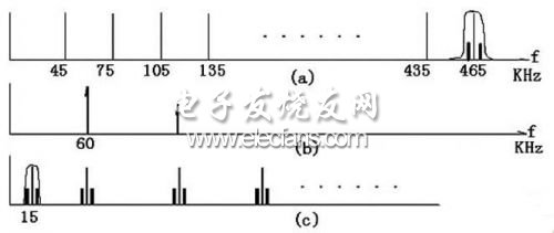
3 Sampling frequency determination and filter implementation According to the above discussion, for a narrowband IF signal of 465 kHz, a 15 kHz signal is generated by sampling at 60 kHz. The signal spectrum relationship before and after sampling is shown in Figure 4.
Figure 4 (a) shows that in addition to the 465 kHz band-pass signal can produce 15 kHz low IF signal by undersampling, other signals can also generate 15 kHz low IF by undersampling, so the 465 kHz IF must be a band-limited filter output. The signal does not allow other signals to be mixed into the sample. Secondly, the frequency domain convolution of the band-limited IF signal and the sampled signal has other spectral components besides the 15 kHz signal spectrum. Therefore, after sampling, the DSP should design a band-pass filter to filter out the spectrum of other signals, such as Figure 4 (c). The baseband speech signal is then obtained by envelope detection.
Litecoin (LTC) is a cryptocurrency created as a fork of Bitcoin in 2011. It uses a hashing algorithm called Scrypt that requires specifically designed mining software and hardware. It is minable, and continues to rank in the top cryptocurrencies for value and trading volume.
Litecoin mining is the process of validating transactions in the blockchain, closing the block, and opening a new one. Litecoin uses the proof-of-work consensus mechanism, which uses computational power to solve the nonce, which is part of the hash, that secures the block. The hash is the alphanumeric sequence of numbers that is encrypted by the hashing algorithm. When the nonce is solved, Litecoin is rewarded.
Litecoin mining became popular in 2011 when Charlie Lee, a software engineer at Google, announced its creation as a Bitcoin fork with modifications intended to help it scale more effectively.
Just like Bitcoin, it can be mined on computers using central processing units and graphics processing units. However, it isn't as profitable or competitive as purchasing an application-specific integrated circuit (ASIC) and joining a mining pool.
Ltc Asic Miner,Antminer L3 Plus Plus,Bitmain Antminer L3 Plus,Bitmain L3 Plus
Shenzhen YLHM Technology Co., Ltd. , https://www.nbapgelectrical.com