The most popular technology in the near future is the finite impulse response (FIR) filter. Just like the conceptual technology that has existed for a long time in audio systems, the development of technology has made them practical. Is this a panacea that we have been waiting for? Can the “Filter Savior†finally bring perfect sound reproduction?
Of course not, but they are still very cool,
Ability to change the rules of the game for certain apps.
This is the first part of a series of articles to examine the use of FIR filters in sound reinforcement systems. There are a lot of tutorials and resources on the Internet to study mathematical operations and deep theory. However, the theoretical knowledge of FIR filters is like a deep well, and it can never be said. In this series, I will combine some "instance" with practical operations and examples to give a general explanation of FIR filter theory. This helps to understand FIR and integrate FIR filtering technology into the project.
Here, the reader needs to have a certain understanding of the basic signal theory, including the time domain and frequency domain concepts involved in the signal analysis of modern audio and acoustic signal analyzers.
What is a FIR filter?
One way to understand the FIR filter is to compare it to the corresponding infinite impulse response (IIR) filter. In general, the IIR can be a digital filter that is analog or similar in behavior to the analog filter. The IIR returns some of the output signal to the input for reprocessing by using "good" feedback.
This "recursive" behavior means that the impulse response of the filter (theoretically) never decays to zero. Of course, the impulse response of such a filter will eventually still decay to zero because the output signal will eventually fall to the noise floor. Since they use feedback signals, the IIR filter may be unstable if not designed properly. All analog filters are IIR filters.
Suppose we use an analog or IIR parametric equalizer to create a Speaker equalization curve (Figures 1 and 2). This includes a high pass, a low pass, and some boost and attenuation in the pass band.
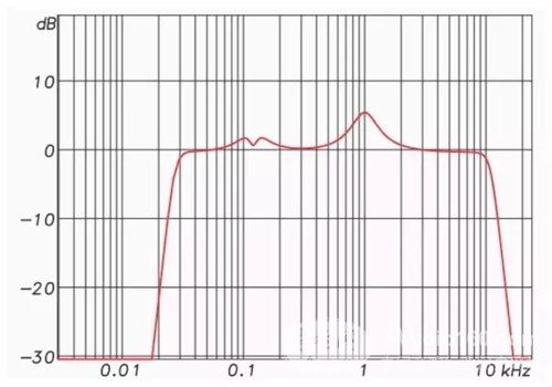
Figure 1: Frequency response amplitude of the equalizer
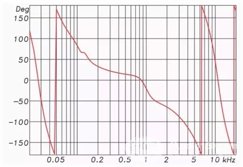
Figure 2: Frequency phase response of the equalizer
Each "bump" in the response represents a phase shift (negative phase angle) at that frequency, and each "fall" represents a reverse phase shift (forward phase) at that frequency. Both the high pass and low pass filters result in the appearance of a negative phase angle, and the angular change is related to the frequency change.
In other words, the amplitude response change is accompanied by a change in phase response. These phase shifts are unavoidable and inherent to the filter. In fact, they can often be predicted by observing the amplitude response. When the amplitude and phase responses are correlated in a predictable manner, this relationship is called "minimum phase" and (sometimes) is an ideal property of the filter.
Because the raised and lowered portions of the speaker's frequency response are typically also the smallest phase. This means that the equalizer completely "equalizes" the response characteristics of the speaker, resulting in a smoother amplitude and phase response. Therefore, in this case, "phase shift" is not a harmful side effect of using a filter, and some people may be aware of this, so it is necessary to "specifically analyze the specific problem."
To clarify, "minimum phase" does not mean that there is no phase shift. It means that the corresponding phase response offset is minimum under a specific amplitude response condition, and the phase response change can be predicted by the frequency response change. The system measurement program can calculate the minimum phase response with a given amplitude response.
Linear phase
The FIR filter can affect the amplitude response without affecting the phase response. On the premise of using the previous filter bank, I replaced the high-pass and low-pass IIR filters with FIR filters with the same amplitude response.
The phase response of such a filter is a straight line on the frequency axis and is therefore referred to as "linear phase." Note that since the phase shifts of the high pass and low pass have been eliminated, only the phase shift due to amplitude boost and attenuation is left (Figure 3).
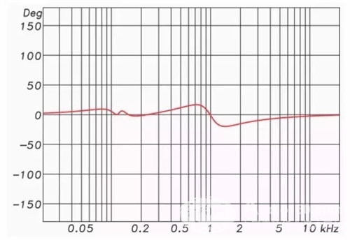
Figure 3: High-pass and low-pass processing using FIR filters
Therefore, for the minimum phase filter, the amplitude and phase responses are mutually influential; for FIR filters, they can be independent. The FIR filter can change the amplitude response without changing the phase response.
From the following, we assume that the IIR filter is the minimum phase filter and the FIR filter can be a linear phase filter. The two types of filters are used to generate identical amplitude response curves, respectively, but their phase response curves may be different. In fact, if you only look at the phase response curves of the FIR high-pass and low-pass filters in my example, you may not think that the filter has been applied.
The biggest advantage of FIR filters is the use of crossover networks. The high-pass filter (HPF) used to protect the high-frequency driver can use a 96 dB/octave or higher slope FIR filter. The phase response of this minimum phase filter (IIR or analog) with such a high slope is very poor because the slope of the phase response curve is also very high when its amplitude response curve is very efficient (see Figure 2).
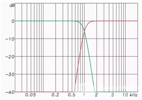
Figure 4: Frequency response of a 48 dB / oct LR crossover network.
These filters are superimposed to produce a completely flat amplitude response.
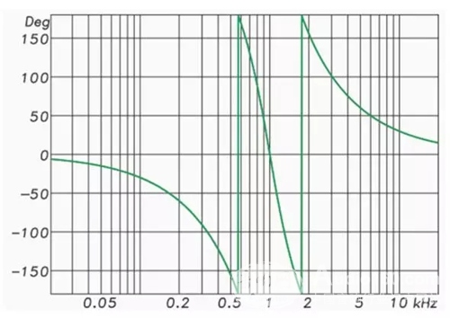
Figure 5: Phase response of a 48dB/oct LR crossover network (filter overlay)

Figure 6: Frequency response of a 96dB/oct crossover network These filters are superimposed to produce a completely flat amplitude response.

Figure 7: Group delay response of the superimposed crossover filter.

Figure 8: Phase response of removing group delay
The slope (order) of the IIR crossover network has practical limits, which are caused by "time contamination" caused by the filter.
Figures 4 and 5 show the amplitude and phase response of a 48 dB / octave Linkwitz-Riley IIR crossover network (HP and LP).
Figure 6 shows the amplitude response of the eighth-order (96 dB/octave) FIR crossover network. Note that the slope of the filter is steeper than the IIR example, and we generally think that such a sharp amplitude response change will cause a severe shift in phase response. One would expect this positive change in amplitude response to be accompanied by a dramatic phase response change.
Figure 7 shows the group delay (GD) response curve after the filter is superimposed, and Figure 8 shows the phase response after removing the excess GD. Note that the phase response is linear.
Using the FIR crossover network, I can even form a "brick wall" attenuation characteristic and a linear phase. Of course, I need to pay some price for the linear phase. This produces a delay of more than 20 milliseconds for the filter. Latency is one of our concerns about using FIR filters.
Two types
As mentioned above, basically two types of filters are used in audio work, each of which usually has multiple terminology descriptions, which are:

These terms have obvious contradictions. For example, an IIR filter can be created in the digital domain. The FIR filter can be the minimum phase. However, these are the "common usage" flags for both filter types and are useful for general discussion. But when it comes to details, it's important to clarify the terminology. What terms will be used in this series? All of this will be used, depending on the context.
Impulse response as filter
Those who make speakers and room measurements are familiar with the impulse response. Although it can be measured by the Dirac pulse played by the recording system, various factors indicate that this technique is completely impractical. Most measurement systems capture the system response and capture the IR response by playing a logarithmic sine wave sweep or "chirp" signal. The IR can be converted to a frequency domain pattern (Fast Fourier Transform or FFT) and displayed as an amplitude/phase map. The amplitude/phase map can be converted (inverse fast Fourier transform or iFFT) back to the time domain for display as a pulse. That is to say, the behavior of the filter can be described in terms of time domain or frequency domain. If you usually use a two-channel FFT measurement platform, then you are already familiar with these concepts.
What does this have to do with the FIR filter? The impulse response of the speakers and the room is FIR filters, which are fully attenuated to zero (or noise floor) due to their limited length. The person using the GratisVolver software to convolve the room impulse response (RIR) using the muffling material is actually using the FIR filter (Figure 9). Therefore, although it may be implemented in software or hardware using the product method in the frequency domain, FIR is sometimes referred to as a "time domain" or "convolution" filter.
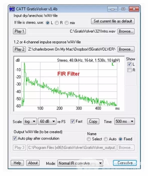
Figure 9:
Using GratisVolver software for the use of sound absorbing materials
The impulse response (FIR filter) of the room is convoluted.
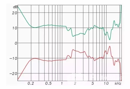
Figure 10:
The frequency response curve (red) of the 3-inch speaker and its conjugate response (green). If the green graphic is used as an equalization filter, the result is a perfect response. (flat frequency response curve and linear phase in the frequency domain, and perfect pulses in the time domain).
The IR of the speaker can be converted to a frequency domain pattern and displayed as frequency amplitude and phase. If the IR is inverted in the frequency domain (upside down), it is the exact conjugate (opposite) of the speaker in amplitude and phase response (Figure 10). If the original and conjugate responses are multiplied, they completely cancel each other out, producing a flat amplitude and phase response curve (frequency domain) or a perfect pulse in the time domain.
This has a big impact on the equalization work - any measurement response can be used as a filter. The FIR "Correction" filter can be used to:
1. Make the speaker's frequency response and phase response curve completely flat, even compensate for anomalies caused by throat reflection, grid effect and edge diffraction.
2. Correct room anomalies, such as boundary effects near the speaker, and (theoretical significance is greater than the actual meaning) room reflection.
3. Optimizing the response characteristics of the linear array by separately processing each array component in the linear array enables beamforming and beam pointing control that cannot be achieved by the analog filter.
The FIR can perform convolution calculations on the program material and use it as a filter. Although this concept has existed for decades, it has only been realized until now. Many DSPs have begun to support the application of FIR filters, allowing real-time convolution calculations for IR.
However, we need to discuss more before we are excited about the “perfect†speaker response and the elimination of room reflections.
The FIR filter provides a "perfect" response at some point in space. However, since the IR characteristics of each point in the space are different, we cannot extend the "correction" to a region. This does not mean that FIR equalization is useless, but it has not yet reached a perfect listening experience. We must accept that in certain circumstances we can benefit in some ways, and as the room size increases, these benefits will become more difficult.
in conclusion
Here are some useful highlights from the introduction of FIR filters:
1. FIR can change the amplitude response of the speaker without changing its phase response. This feature allows us to use a very steep slope divider without causing a phase shift. The cost of obtaining this linear phase characteristic is an increase in delay.
2. The impulse response obtained by any measurement can be used as an FIR filter. This feature allows us to “listen†to room measurement data, such as using GratisVolver software or performing equalization optimizations that are not possible with analog filters. These tasks can even be done in flight, such as echo cancellation optimization of the conference system.
3. FIR can be embedded in software for convolution calculations. For example, use the GratisVolver to "listen" to the room impulse response.
4. FIR implants hardware devices for real-time signal processing. There are already several DSP products that support user-defined FIR filters.
So in the field of sound reinforcement systems, the main uses of FIR are:
Crossover network
2. Speaker equalization correction.
3. “Listen†to the room response through the convolution calculation software, whether this response data is generated or measured by the room modeling program.
4. For beamforming in linear array systems.
The audio filter is no longer limited to a collection of capacitors, inductors, and resistors, or an equivalent circuit that uses the integrated circuit to achieve the same function. They can also be generated by measurements or mathematical algorithms and processed in real time using advanced digital signal processing techniques.
▶ In Part 2, I will introduce more basics of FIR filters and show several ways to generate “brick-wall linear phase†FIR filters for crossover networks, including some measurements on real speakers. Stay tuned!
With more than 15+ yrs rich MFG experience, you can definitely trust in and cooperate with.
Provide you with the supply of Personal Protective Equipment. to help you safely get back to your daily routine.
Our products include pulse Oximeter Finger, Forehead Thermometer, Automatic foam soap dispenser, etc.
Our strict quality control protocol thoroughly vets every aspect of production, storage, and shipments all the way way to our end customers.
nano spray gun, nano spray gun disinfectant, nano spray machine
TOPNOTCH INTERNATIONAL GROUP LIMITED , https://www.mic11.com