Widely used in production machinery, the speed control method that does not change the synchronous speed is the rotor string resistance speed regulation of the wound motor, the chopper speed regulation, the cascade speed regulation, and the application of the electromagnetic slip clutch, the fluid coupling, the oil film clutch, etc. Speed ​​regulation. The multi-speed motor that changes the synchronous speed and has the number of stator pole pairs is changed. The variable frequency speed regulation of changing the stator voltage and frequency can be adjusted without the commutation motor.
From the point of view of energy consumption during speed regulation, there are two methods of high-efficiency speed regulation and low-efficiency speed regulation: high-efficiency speed regulation means that the slip rate is constant, so there is no slip loss, such as multi-speed motor, frequency control And a speed control method that can recover the slip loss (such as cascade speed regulation, etc.). The speed control method with slip loss is inefficient speed regulation, such as the rotor string resistance speed regulation method, the energy is lost in the rotor circuit; the electromagnetic clutch speed control method, the energy loss in the clutch coil; the hydraulic coupling speed regulation The energy loss is in the oil of the fluid coupling. Generally, the slip loss increases as the speed range increases. If the speed range is not large, the energy loss is small.
According to the aforementioned knowledge, for AC motors, there are:
![]()
![]()
among them, ![]() ——Rotating magnetic field speed
——Rotating magnetic field speed
![]() ——Stator winding AC power frequency
——Stator winding AC power frequency
![]() ——The number of poles of three-phase asynchronous motor
——The number of poles of three-phase asynchronous motor
![]() ——Three-phase asynchronous motor rotor speed
——Three-phase asynchronous motor rotor speed
![]() - slip rate
- slip rate
Eliminated by the above two ![]() , you can get:
, you can get:
![]() .................................................................. (Formula 7-5-1)
.................................................................. (Formula 7-5-1)
According to the above formula, there are three ways to adjust the speed of the asynchronous motor, namely: 1 change the number of pole pairs of the stator winding ![]() ; 2 change the slip rate
; 2 change the slip rate ![]() ;3 change the power frequency
;3 change the power frequency ![]() . For synchronous motors, the slip rate
. For synchronous motors, the slip rate ![]() It only has two speed adjustment methods. There are many ways to adjust the AC speed in practical applications. The following is a brief introduction to several commonly used methods:
It only has two speed adjustment methods. There are many ways to adjust the AC speed in practical applications. The following is a brief introduction to several commonly used methods:
Variable pole speed regulation
This type of speed regulation is only used in specially produced multi-stage multi-speed asynchronous motors. Through the different combinations of windings, three speeds of two, three and four poles can be obtained. The speed change of this speed control mode is graded, and it is only suitable for some special applications, and can only achieve the purpose of large-scale coarse adjustment. . The learning unit of the third chapter of the course introduces the variable speed control of the two-speed motor. Other speed control lines similar to the multi-stage multi-speed motor are similar.
Rotor string resistance speed regulation
This speed regulation method is only applicable to the wound rotor asynchronous motor. It changes the slip rate of the motor by changing the resistance value of the resistor connected in the rotor circuit, thereby achieving the purpose of speed regulation. Since the resistance of the external series resistor can be changed in multiple stages, speed regulation of various speeds can be realized (in principle, stepless speed regulation can also be realized). However, since the series resistance consumes power, the efficiency is low, and the mechanical characteristics of the speed regulation mode are soft, and it is only suitable for occasions where the speed regulation performance is not high.
Cascade speed regulation
This type of speed regulation is only applicable to a wound-type asynchronous motor, which is a method in which the slip power is fed back to the power grid through a certain electronic device. It is widely used in fan and pump transmission systems.
Voltage regulation
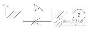
Figure 1 Schematic diagram of voltage regulation
As shown in Fig. 1, the thyristors are connected in anti-parallel to form an AC speed control circuit. By adjusting the firing angle of the thyristors, the terminal voltage of the asynchronous motor is changed to adjust the speed. This way also changes the slip rate ![]() The slip power is consumed in the rotor circuit, and the efficiency is low, which is suitable for a special rotor motor (for example, a high slip motor such as a deep groove motor). Usually, this method of speed regulation should constitute a closed loop of speed or voltage for practical application.
The slip power is consumed in the rotor circuit, and the efficiency is low, which is suitable for a special rotor motor (for example, a high slip motor such as a deep groove motor). Usually, this method of speed regulation should constitute a closed loop of speed or voltage for practical application.
Electromagnetic speed regulation asynchronous motor
This system transfers mechanical power between the asynchronous motor and the load through electromagnetic coupling, adjusts the excitation of the electromagnetic coupler, and adjusts the slip rate. ![]() The size of the wheel thus achieves the purpose of speed regulation. The speed control system is simple in structure and inexpensive, and is suitable for use in a simple adjustment system. However, its slip power is consumed on the coupler and is inefficient.
The size of the wheel thus achieves the purpose of speed regulation. The speed control system is simple in structure and inexpensive, and is suitable for use in a simple adjustment system. However, its slip power is consumed on the coupler and is inefficient.
Frequency
Changing the power supply frequency allows the asynchronous motor to achieve different synchronous speeds. The speed control method of using an inverter to power an asynchronous motor has been rarely used. At present, a large amount of static inverter power supply using a semiconductor device is used. At present, such speed control methods have become the mainstream of AC speed regulation development.
Detailed explanation of several speed control methods for asynchronous motors
Speed ​​control method
From the speed of the asynchronous motor:
n=n1(1-S)=60(f1/P)(1-S)
It can be seen that to change the speed of the asynchronous motor, we can start from the following three aspects:
1. Change the pole pair number P of the stator winding of the asynchronous motor to change the speed n1 of the rotating magnetic field of the stator, that is, the so-called variable pole speed regulation (not uniform speed regulation).
2. Change the frequency of the power supply connected to the motor to change n1, the so-called variable frequency speed regulation;
3. Change the slip S of the motor.
Among them, there are many ways to change the slip rate S. When the total braking torque of the load is constant, the electromagnetic torque balanced with it is also unchanged. Therefore, it can be seen from the electromagnetic torque parameter expression (slightly) that when the frequency f1 and the pole pair P are constant, The slip ratio S is a function of physical quantities such as stator terminal voltage, stator resistance, and leakage reactance. Therefore, there are several methods for changing the slip ratio S:
(1) changing the terminal voltage applied to the stator, for which a voltage regulator is required for voltage regulation;
(2) changing the stator resistance or leakage reactance, for which a resistor or a reactor must be applied in series with the stator;
(3) changing the rotor resistance, for which a winding type motor is used, and an external resistor is connected in the rotor circuit;
(4) Change the rotor reactance, for which a reactance or capacitor must be connected in the rotor circuit.
(5) Introducing an applied potential of the slip ratio f2=Sf1 in the rotor circuit. For this purpose, another motor must be used to supply the required applied potential. The motor can be coaxial with the original motor or not coaxial. Several motors are electrically connected in series to achieve the purpose of speed regulation, which is called cascade speed regulation. Cascade speed regulation can be replaced by a thyristor speed regulation. The basic principle is as follows: firstly, the slip frequency AC current in the rotor circuit of the asynchronous motor is rectified into a direct current by a semiconductor rectifier, and then the DC is converted into an alternating current through the thyristor inverter, and sent back to the alternating current grid. At this time, the voltage of the inverter is equivalent to the potential applied to the rotor circuit, and the inverter angle of the inverter is controlled, and the voltage of the inverter can be changed, that is, the potential applied to the rotor circuit is changed, thereby realizing the speed regulation. the goal of.
From the above analysis, it can be seen that there are many speed control methods for asynchronous motors. The following three main types are introduced, namely, variable pole speed regulation, frequency conversion speed regulation and changing rotor resistance speed regulation.
Variable pole speed regulation
Since the slip rate S of the general asynchronous motor during normal operation is very small, the motor speed n=n1 (1-S) is determined by the synchronous speed n1. It can be seen from n1=60f1/P that when the power supply frequency f1 is constant, the pole pair P of the stator winding is changed, and the synchronous rotation speed n1 changes. For example, the number of pole pairs is doubled, and the synchronous rotation speed is decreased by half. The speed of the motor is also reduced by about half. Obviously, this speed control method can only change the speed at the first level and one level, instead of smoothing the speed.
The pole-changing motor generally uses a squirrel cage rotor, because the pole pair number of the squirrel-cage rotor can automatically change with the change of the pole number of the stator pole, so that the pole pairs of the stator and rotor magnetic fields are always equal and the average electromagnetic rotation is generated. Moment. In the case of a wound rotor, when the number of stator pole pairs is changed, the rotor winding must be changed accordingly to obtain the same pole pair number as the stator, which is inconvenient.
In order to make the stator have two pole pairs, it is easy to obtain two sets of stator windings with different pole pairs, one set at a time, the so-called double winding poles. Obviously, this is a very uneconomical way. It is only used in special circumstances. The ideal solution is to install only one set of stator windings and change the winding connection to obtain two or more pole pairs, so-called single-winding poles. For the case of doubling ratio (such as 2/4 pole, 4/8 pole, etc.), single winding has been adopted for a long time. With the development of science and technology, non-magination ratio (such as 4/6 pole, 6/8) The use of single-winding poles is also widely used for three-speed (such as 4/6/8, etc.).
Frequency
When the frequency f1 of the power source changes, the synchronous speed n1=60f1/P changes in proportion to the frequency, so that the rotation speed n of the motor also changes, so that the rotation speed of the asynchronous motor can be smoothly adjusted by changing the power supply frequency.
The frequency conversion speed regulation is divided into U/f control, slip frequency control, vector control and direct torque control according to different control modes.
(1) U/f control. U/f control is to obtain the ideal torque-speed characteristics, based on the idea of ​​changing the power frequency to adjust the speed while ensuring that the magnetic flux of the motor is unchanged. General-purpose inverters basically use this control method. U/f control inverter structure is very simple, the disadvantage is that the inverter adopts open-loop control mode, which can not achieve high control performance, and must compensate torque at low frequency to improve low-frequency torque characteristics.
(2) Slip frequency control. Slip frequency control is a control method that directly controls the torque. It is based on the U/f control, and the frequency of the power supply corresponding to the actual speed of the asynchronous motor is known, and the inverter is adjusted according to the desired torque. By outputting the frequency, the motor can have a corresponding output torque. This kind of control method requires the installation of a speed sensor in the control system, and sometimes a current feedback to control the frequency and current, so it is a closed loop control method. This method can make the frequency converter have good stability and good response characteristics for rapid acceleration and deceleration and load variation.
(3) Vector control. Vector control is to control the magnitude and phase of the stator current of the motor through the vector coordinate circuit to control the excitation current and torque current of the motor in the d, q, O coordinate system respectively, and then achieve the purpose of controlling the motor torque. By controlling the order of action of each vector, the time, and the action time of the zero vector, various PWM waves can be formed to achieve various control purposes, such as forming a PWM wave with the least number of switching times to reduce switching loss. At present, the vector control methods actually applied in the frequency converter mainly include a vector control method based on the special frequency control and a vector control method based on the speed sensorless.
The vector control method based on the slip frequency is consistent with the steady-state characteristics of the slip frequency control method, but the vector control based on the slip frequency also controls the phase of the motor stator current through coordinate transformation. Make it meet certain conditions to eliminate fluctuations in the torque current transition. Therefore, the vector control method based on the slip frequency can be greatly improved in output characteristics compared to the slip frequency control method. However, this control method is a closed loop method, and a speed sensor needs to be mounted on the motor, so the application range is limited.
The speed sensorless vector control is controlled by coordinate transformation to control the excitation current and the torque current respectively, and then by controlling the voltage and current on the stator winding of the motor to identify the rotational speed to achieve the purpose of controlling the excitation current and the torque current. This control mode has a wide speed range, large starting torque, reliable operation and convenient operation, but the calculation is complicated, and a special processor is generally required for calculation. Therefore, the real-time performance of this method is not too ideal, and the control accuracy is affected by the calculation accuracy.
(4) Direct torque control. Direct torque control uses the concept of space vector coordinates, analyzes the mathematical model of the AC motor in the stator coordinate system, controls the flux linkage and torque of the motor, and detects the stator flux by detecting the stator resistance, thus eliminating the need for Complex transformation calculations such as vector control, the system is intuitive and concise, and the calculation speed and accuracy are improved compared with the vector control method. Even in the open loop state, it can output 100% of rated torque, and it has load balancing function for multiple drives that supply power to multiple motors from one inverter.
The frequency conversion speed regulation is obviously used for the energy saving effect of the fan and the pump type machinery.
The above various types of control are applicable to special motors for variable frequency speed regulation. The variable frequency motor is developed from a traditional squirrel cage motor, which converts the traditional motor fan into a separate fan and improves the insulation performance of the motor winding.
Rotor loop string resistance speed regulation
The varistor speed regulation in the rotor circuit series is only applicable to the wound asynchronous motor. The wiring diagram during speed regulation is the same as that at startup. The difference is that the general starting varistor works for a short time, and the varistor for speed regulation should work for a long time.
The physical process during speed regulation is the same as that of the DC motor in the armature circuit. At the initial moment when the resistance of the varistor increases, the rotational speed of the motor does not change too much, so the rotor current decreases, and accordingly the electromagnetic torque also decreases, the rotational speed of the motor begins to decrease, and the potential of the rotor begins to increase, and the rotor current returns. increase. This process continues until the rotor current increases to balance its corresponding electromagnetic torque and total load torque, at which time the motor operates stably at a lower speed.
When the rotor circuit is connected to the speed regulating resistor, if the total load torque of the motor remains unchanged, the motor moves from one operating point to another, and the slip rate increases from S1 to S2, and the speed is from n1 (1-S1). ) Drop to n1 (1-S2). Increase the speed control resistor, the lower the speed.
From the rotor circuit string resistance speed regulation curve (slightly) can be seen within a certain range of speed control resistance variation, the size of the speed regulation range varies with the weight of the load; in the case of no-load speed regulation, the speed regulation range is very small, the actual The purpose of speed regulation is not up to the limit.
In addition, in the constant torque speed regulation, from the electromagnetic torque parameter expression (slightly), the slip rate s will change proportionally with the total resistance of the rotor circuit, and the total resistance will double. The difference is also doubled, so it can be seen according to the equivalent circuit: constant torque, constant current, input current, air gap magnetic field and electromagnetic power are constant, regardless of the magnitude of the series resistance of the rotor circuit. Therefore, if the lower the rotational speed, that is, the larger the slip ratio, the larger the resistance in the rotor circuit is required, and the greater the copper loss of the rotor, the lower the motor efficiency. It can be seen that this method of speed regulation is very uneconomical, and the output power reduced by the reduced speed is all consumed by the copper consumption of the speed regulating resistor. Another disadvantage is that the mechanical characteristics of the motor become soft after the rotor is added with resistance, that is, the rotational speed will change significantly when the load changes.
It can be seen that there are many shortcomings in the rotor circuit string resistance speed regulation, but because of the relatively simple and smooth speed regulation, the winding motor of the medium and small capacity is still used a lot. For example, the bridge crane of the AC power source is almost used. This method speeds up.
JBL Battery,JBL Charge Battery,JBL Speaker Battery,JBL Charge 3 Battery
Shenzhen Sunwind Energy Tech Co.,Ltd , https://www.sunwindbatterylm.com