With the rapid development of microelectronics technology, the scale of integrated circuits has increased rapidly according to Moore's Law (the number of transistors integrated on microchips has doubled every 18 months), and System OnChip (SOC) technology has become an international ultra-large scale integrated circuit. development trend. In the design of SOC system, in order to form products quickly and stably, IP core accumulation and multiplexing technology has gradually become the first choice of various chip manufacturers. In this context, IP multiplexing technology has become an important branch of integrated circuit design. Many design manufacturers are paying more and more attention to the IP core design and accumulation of the company while purchasing IP cores of other companies.
The DMA controller is one of the common bus devices, and many manufacturers have their own DMA controller IP core. For example, ARM, the leader of embedded processors, has its own DMA controller solution available to customers. In addition, chip manufacturers like Freescale and Fujitsu have their own solutions. This paper introduces the IP core design of DMA controller based on AHB bus, which is based on one of ARM bus. It briefly describes the process of IP core design and the places that need to be paid attention to.
DMA controllerFunctional description
In general, the function and structure of the DMA controller is determined by the specific system structure of the unit. But as an IP, the DMA controller has its generality. DMA refers to the I/O method in which an external device directly reads and writes to a computer memory. In this way, the reading and writing of data does not require the CPU to execute instructions, nor does it pass through the internal registers of the CPU, but uses the data bus of the system, and the peripherals directly write or read the memory, thereby achieving an extremely high transfer rate. Now DMA can also perform data operations directly between memory or peripherals. The importance of DMA technology is that it does not require CPU intervention when using it for data access, which increases the efficiency of the system's execution of applications. Another benefit of using DMA to transfer data is that data is transferred directly between the source and destination addresses, and does not need to be an intermediary.
The general purpose DMA controller should have the following features:
1. Program the DMA transfer mode and the address area of ​​the memory it is accessing.
2. Mask or accept DMA requests from peripherals or software. When multiple devices request at the same time, priority queuing is also required, first responding to the most advanced request.
3. Propose a bus request to the CPU or bus arbitration device.
4. Receive the bus response signal and take over the bus control.
5. Direct transfer of data between peripherals and memory, peripherals and peripherals or memory under the management of the DMA controller.
6. Perform address modification and transmission amount counting during transmission. When the requested data is transferred, the bus request is revoked and the bus control is returned.
In short, the DMA controller can take over the bus on the one hand, and directly read and write between the I/O interface and the memory, that is, it can be regarded as the main device of the bus like the CPU, which is the fundamental difference between the DMA and other peripherals; On the other hand, as an I/O device, its DMA control function is officially set by initial programming. When the CPU writes or reads it, it becomes a slave to the bus like any other peripheral.
As a dedicated DMA controller, there are specific functional requirements. For example, for the AHB bus, you need to support Burst operations. On the other hand, most embedded systems or computer systems that support operating systems now use virtual memory technology. The use of this technology makes it possible to see that there is no one-to-one mapping between memory addresses and physical addresses at the operating system level. Continuous memory addresses on the operating system level are not necessarily continuous in real physical memory. But the DMA controller does not necessarily understand this phenomenon. To solve this problem and improve transmission efficiency, most DMA controllers used in advanced embedded systems support scatter/collective LLI (LogicLinkItem) technology.
Design indicator
The main indicators of the DMA controller are as follows:
$16 DMA channels, 6 of which are independent software channels, and the other 10 are channels for hardware and software multiplexing.
The $DMA read data is performed independently of the write data.
Each channel is independently programmed and initialized independently.
$Support software reset.
$ Full support for the AHB bus protocol.
$LLI technology is supported.
Overall designThe DMA controller mainly includes the following modules, and its structure is shown in Figure 1.
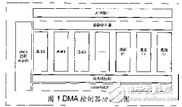
$APB interface module: This part mainly implements the APB bus read/write protocol and configures the registers of the DMA controller through ARM.
$Control Register Module: This part is configured through the APB bus to obtain control information of the DMA controller. The module is mainly composed of a command control register, a status register and an interrupt register.
$DMA Control State Machine Module: This module is the core part of the DMA controller. It is responsible for initiating and aborting each DMA transfer, and is responsible for state transitions during each DMA transfer.
$Channel Module: This module contains 16 channels, 10 of which are software and hardware multiplexed, and the other 6 are software-specific. In addition to the conventional register set, the former is also responsible for detecting hardware DMA transfer requests; while the latter does not have this part of the function, but the latter must support the LLI function. The conventional channel register set consists of the source address, destination address, transmission length, and channel control registers of each channel.
$Priority Control Module: This module has a status register and a request register. ARM determines the priority order of each channel through programming. When multiple DMA requests occur at the same time, this module determines which request is preferentially responded.
$AHB bus interface module: This module is responsible for implementing the AHB bus read and write protocol.
Working principle and processAs a DMA controller has its particularity, mainly reflected in it is both the bus slave device and the bus master device. Therefore, the DMA controller has two main states - idle state and active state. When the DMA controller is in the idle state, it is equivalent to a slave device of the bus and is managed and controlled by the ARM. ARM configures the registers of the DMA controller programmatically.
The present invention provides a method for controlling the temperature of a flue-cured electronic cigarette and a flue-cured electronic cigarette. The flue-cured electronic cigarette includes an N-section heating body, where N is an integer greater than 1, and the heating body is used for heating tobacco. The method for controlling the temperature of the flue-cured electronic cigarette includes: the flue-cured electronic cigarette heats the i-th heating body, and i is an integer greater than 0 and less than N; after the first preset time, the flue-cured electronic cigarette pairs the i+ The first stage heating body is heated; after the second preset time, the flue-cured electronic cigarette stops heating the i-th stage heating body, and continues to heat the i+1th stage heating body. The technical solution solves the problem of unbalanced smoke output of flue-cured electronic cigarettes during multi-stage heating.The present invention provides a method for controlling the temperature of a flue-cured electronic cigarette and a flue-cured electronic cigarette. The flue-cured electronic cigarette includes an N-section heating body, where N is an integer greater than 1, and the heating body is used for heating tobacco. The method for controlling the temperature of the flue-cured electronic cigarette includes: the flue-cured electronic cigarette heats the i-th heating body, and i is an integer greater than 0 and less than N; after the first preset time, the flue-cured electronic cigarette pairs the i+ The first stage heating body is heated; after the second preset time, the flue-cured electronic cigarette stops heating the i-th stage heating body, and continues to heat the i+1th stage heating body. The technical solution solves the problem of unbalanced smoke output of flue-cured electronic cigarettes during multi-stage heating.
E-Cigarette Starter Kits,small e cigarette starter kit,mini e cigarette starter kit,e cig starter kit near me,cheapest e cigarette starter kit, e cigarette starter kits,electronic cigarette starter kits
Suizhou simi intelligent technology development co., LTD , https://www.msmsmart.com