Frequency conversion speed regulation technology is an important development direction of modern electric drive technology, and as the core of variable frequency speed control system - the performance of frequency converter is becoming more and more the decisive factor of the speed control performance, except for the "innate" manufacturing process of the inverter itself. In addition to the conditions, it is also very important to control the inverter. Based on the industrial reality, this paper reviews the characteristics of various inverter control methods in recent years, and looks forward to the future development direction.
Introduction to the inverter1) The basic structure of the inverter
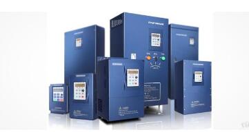
The frequency converter is a device that converts a commercial power supply (50 Hz or 60 Hz) into an AC power supply of various frequencies to realize variable speed operation of the motor, wherein the control circuit completes control of the main circuit, and the rectifier circuit converts the alternating current into direct current, and the middle of the direct current The circuit smoothes the output of the rectifier circuit, and the inverter circuit re-inverts the DC power into AC power. For a frequency converter such as a vector control inverter that requires a large amount of calculations, sometimes a CPU for torque calculation and some corresponding circuits are required.
2) Classification of the inverter
There are various classification methods of frequency converters. According to the main circuit working mode, they can be divided into voltage type inverters and current type inverters. According to the switch mode classification, they can be divided into PAM control inverters, PWM control inverters and high carrier frequencies. PWM control inverter; according to the working principle, it can be divided into V/f control inverter, slip frequency control inverter and vector control inverter; according to the purpose classification, it can be divided into general inverter, high performance special inverter, High frequency inverter, single phase inverter and three phase inverter.
For the control method, it should be selected according to the specific requirements of the production machinery.
1. Quadratic law load For the quadratic law load of centrifugal fan, water pump and air compressor, V/F control mode is generally suitable. Because the V/F control mode has a low excitation U/f line, it can save energy even when running at low frequencies. The vector control method is essentially a control method that keeps the motor always maintained at the rated magnetic flux, and it is impossible to achieve low excitation. 2. Constant torque load
(1) For loads with frequent load rate changes and small speed range, it is generally better to choose no feedback vector control, because the “torque boost†of V/F control mode is not easy to preset, but it is adopted. When there is no feed vector control mode, you must pay attention to:
1) Self-measurement of motor parameters must be performed.
2. If the minimum operating frequency is below 5 Hz, you need to know the low frequency operation characteristics of the selected inverter brand. Some inverters are often not stable enough when running at low frequencies without feedback vector control.
(2) For loads with stable load rate, V/F control mode can be adopted, because a cheaper general-purpose inverter without vector control function can be selected.
(3) The hoisting machinery adopts the “with feedback vector control†mode, and some of the frequency converters can adopt the “no feedback vector control†mode.
3, constant power load
(1) The winding machine can adopt the V/F control mode or the “no feedback vector control†mode.
(2) Metal cutting machine tools Because of the high dynamic response requirements, it is best to use the "with feed vector control" method.
Constant torque load: P = ML *n / 9550, ML is constant torque, power is proportional to the speed of constant power load: ML = 9550P / n, power P is constant, torque is inversely proportional to speed.
1. U/f=C sinusoidal pulse width modulation (SPWM) of inverter control mode
The SPWM control mode of the inverter is characterized by simple control structure, low cost, good mechanical properties and hardness, which can meet the requirements of smooth speed regulation of general transmission, and has been widely used in various fields of the industry. However, in this mode of control, at low frequencies, the torque is affected by the voltage drop of the stator resistance due to the lower output voltage, which reduces the maximum output torque. In addition, its mechanical characteristics do not have DC motor hard, dynamic torque capability and static speed regulation performance are not satisfactory, and the system performance is not high, the control curve will change with the load change, the torque response is slow, the motor turns The moment utilization rate is not high, and the performance is degraded due to the existence of the stator resistance and the dead zone effect of the inverter at a low speed, and the stability is deteriorated. Therefore, people have also studied vector control frequency control.
2. Voltage space vector of inverter control mode (SVPWM)
The SVPWM control mode of the inverter is based on the overall three-phase waveform generation effect. For the purpose of approaching the ideal circular rotating magnetic field trajectory of the motor air gap, the three-phase modulation waveform is generated at one time, and the inscribed polygon is approximated by the circle. After practice, it has been improved, that is, the introduction of frequency compensation can eliminate the error of speed control; estimate the magnitude of the flux linkage through feedback to eliminate the influence of stator resistance at low speed; close the output voltage and current to improve the dynamic accuracy and stability. However, there are many control circuit links and no torque adjustment is introduced, so the system performance has not been fundamentally improved.
3. Vector control (VC) mode of inverter control mode
The VC control mode of the inverter is to convert the stator currents Ia, Ib, Ic of the asynchronous motor in the three-phase coordinate system to the AC current Ia1Ib1 in the two-phase stationary coordinate system by three-phase-two-phase transformation. By directing the rotation transformation according to the rotor field, it is equivalent to the direct current Im1, It1 in the synchronous rotating coordinate system (Im1 is equivalent to the excitation current of the DC motor; It1 is equivalent to the armature current proportional to the torque), and then imitating the DC motor The control method obtains the control quantity of the DC motor, and realizes the control of the asynchronous motor through the inverse transformation of the corresponding coordinates. The essence is that the AC motor is equivalent to a DC motor, and the two components of speed and magnetic field are independently controlled.
By controlling the rotor flux linkage and then decomposing the stator current to obtain two components of torque and magnetic field, coordinate transformation is used to realize orthogonal or decoupling control. The proposed vector control method has epoch-making significance. However, in practical applications, because the rotor flux linkage is difficult to accurately observe, the system characteristics are greatly affected by the motor parameters, and the vector rotation transformation used in the equivalent DC motor control process is complicated, making the actual control effect difficult to achieve the ideal analysis. result.
4. Direct torque control (DTC) mode of inverter control mode
The DTC control method of the frequency converter originated from Professor DePenbrock of Ruhr University in Germany in 1985. He first proposed the direct torque control frequency conversion technology. This technology largely solves the above-mentioned shortcomings of vector control, and has been rapidly developed with novel control ideas, simple and clear system structure, and excellent dynamic and static performance.
At present, this technology has been successfully applied to high-power AC drives for electric locomotive traction. The direct torque control directly analyzes the mathematical model of the AC motor in the stator coordinate system to control the flux linkage and torque of the motor. It does not require the AC motor to be equivalent to a DC motor, thus eliminating many of the complex calculations in vector rotation transformation; it does not require the control of a DC motor, nor does it need to simplify the mathematical model of the AC motor for decoupling.
5, the matrix control mode of the inverter control mode
The matrix type AC-AC method of the inverter eliminates the intermediate DC link, thus eliminating the bulky and expensive electrolytic capacitor. It can achieve a power factor of l, the input current is sinusoidal and can operate in four quadrants, and the system has a high power density. Although the technology is not yet mature, it still attracts many scholars to study in depth. The essence is not to indirectly control the current, flux linkage, etc., but to achieve the torque directly as the controlled amount.
The specific method is:
1) Control the stator flux linkage to introduce the stator flux linkage observer to realize the speed sensorless mode;
2) Automatic identification (ID) relies on accurate motor mathematical model to automatically identify motor parameters;
3) Calculate the actual value, calculate the actual torque, stator flux and rotor speed in real time according to the stator impedance, mutual inductance, magnetic saturation factor, inertia, etc.;
4) Realize the Band-Band control. The Band-Band control of the flux linkage and torque generates a PWM signal to control the inverter switching state.
Matrix AC-AC has fast torque response (2ms), high speed accuracy (±2%, no PG feedback), high torque accuracy (+3%), and high starting torque. High torque accuracy, especially at low speeds (including 0 speed), can output 150% to 200% torque.
Of course, seeing this is not to say that the inverter can be fully understood. To better understand the working principle of the inverter, you need to understand the above knowledge and decompose it into reality. Then you can understand the inverter. The working principle (the legendary nonsense: practice the truth).
Shenzhen Innovative Cloud Computer Co., Ltd. , https://www.xcypc.com