Everyone seems to like to divide the main Speaker system into left/right parts on a horizontal plane, but divide them into upper/lower parts on a vertical plane? I am afraid I don't like it so much.
In applications such as cruises or runways, we use a separate multi-set main speaker system configuration on a horizontal plane.
Although it is not possible to use more than two modules for expansion, a system configuration of multiple sets of main speakers can also be used in a vertical plane.
Whether it is necessary to expand in the vertical plane depends on the shape of the room, which refers to a very special room shape: picking the stage. Next, let's take a look at the challenges faced in this battle.
Here we are talking about the left/right (L/R) main speaker system, not including the low-position center speaker (which happens to be the area where the band is located). When the center main speaker system covers the pick-up area, the L/R main speaker system plays a side-compensating role in the pick-up area closer to it, and there is a delay between the two speaker systems. The problem. The only problem is when the L/R speaker system and the center speaker system are uncoupled. We all want the band members to stay together during the show, but sometimes they need to move freely in different directions (see Figure 1).
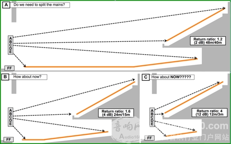
Figure 1: This application example raises the question of whether the main speaker system should be split into two parts. In these three examples, the mounting height of the main speaker system and the shape of the picker remain unchanged.
Single slope and double slope
The typical listening area is a slope that gradually rises with increasing distance. We can solve the problem of the coverage of the slope by asymmetrically coupled point source speaker array design. The simplest listening area is a slope with a constant slope, and the listening area is gradually increased in proportion to the increase in distance. Unfortunately, we are usually faced with more complex situations, such as the far slope of the listening area being steeper than the near end. However, even in the case of a large change in the lift slope, a coupled point source speaker array can still solve the coverage problem by an asymmetric design.
When the listening area of ​​the pick-up was increased to two layers, the trouble began to appear. We are now faced with a double-layered bevel, in which case an uncoupled approach is required. There are two common ways to cope: treat the two bevels as a composite bevel (keep the coupling of the speaker array) or treat them as two separate bevels and cover them independently (uncoupled).
We can build a speaker array with the correct curvature based on the details of the pick and maintain the coupling state. The problem in this way is that the sound pressure level changes (the sound in the front of the stage is relatively large) and the frequency response changes (the front side of the stage produces reflection); the advantage is that all the sound sources are closely arranged in Together, a wider frequency response can be obtained in the coupling region. As the depth of the pick-up increases, the magnitude of the change in sound pressure level increases accordingly; if the front of the pick-up is a higher reflective surface, the magnitude of the change in frequency response will also increase. These two issues are exactly what we need to avoid.
What size pick is too deep? How do you know that the front of the stage will cause us trouble? Only after fully understanding the acoustic environment of the stage can you come up with a solution.
The double beveled listening area has four important coverage target key points: VTOP1 (top of the vertical plane), VBOT1 (bottom of the vertical plane), VTOP2 and VBOT2. Each key point has an independent angle and range relationship with the main speaker system, and each pair of key points has an independent angular expansion relationship and a range ratio. The problem we need to solve is precisely due to the intrinsic relationship between these key points (VBOT1-TOP2). Now let's look at the results of the numerical changes in the intrinsic relationship between key points (see Figure 2).
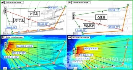
Figure 2: An application example of a vertical double-slope listening area. Multiple shallower stages exhibit a near-symmetric (1:1) turndown ratio, while the ground's turndown ratio is very asymmetrical (>2:1). In this case, the two slopes can be covered separately.
Let's start with two identically sized bevels, one bevel directly above the other. Each bevel has a 20 degree angular spread and a 2:1 turndown ratio. The speaker array is located in the middle of the vertical plane, so it can cover VTOP1 (+20 degrees) to VBOT2 (-20 degrees) with a 2:1 turndown ratio (6dB). The range ratio corresponding to VBOT1 (+0 degrees) to VTOP2 (-0dB) is also 2:1.
We can also use a speaker with an angle of 80 degrees to point it to the topmost seat, thereby solving the 6dB range ratio problem in a beveled listening area with an angle of 40 degrees. However, how do we solve the 6dB range ratio problem in the 0 degree extended area? Of course, since the stage must be thick enough to provide sufficient load-bearing, it is impossible to have an angular expansion of 0 degrees, but this expansion angle can be very, very small.
Return coefficient
"Listen, the speakers! Tightly united. Our mission is to keep moving forward and step closer to the top 20-degree area, then move on immediately and repeat this action."
If you don't believe that this is an impossible task, then the ever-increasing range ratio will allow you to surrender. A wider pick will add more difficulties to us, but if there is such a stupid friend, do you still need an enemy?
Let's make a little change to the shape of the previous pick and then look at the results. Move the leading edge of the upper stage back until the leading edge of the upper stage is aligned with the rear edge of the lower stage.
Now let's see what happened. The angular spread between VBOT1 and VTOP2 is still 0 degrees, but the turn ratio between them becomes 1:1, and there is no longer a jagged dividing line between them. At this point we can use a main speaker to cover the two bevels.
When the relationship between the two key points changes, there is no pick in the listening area. This simulation process provides us with an important piece of information: the return factor - an important reference for the need to segment the speaker array.
Each å‹ of the upper listening zone moving forward increases the discontinuity between VBOT1 and VTOP2. The shape change of the listening area results in angular isolation of the listening area coverage, and a speaker cannot satisfy this coverage requirement. The return factor (in dB) shows the difference in sound pressure level between the pick-up areas, and this difference is what we need to eliminate.
As you can see from the figure below, the return factor is smaller in the shallower pick-up area and can still be covered with a speaker array. When the return factor is 6dB or higher, a single speaker array cannot be evenly covered (see Figure 3).
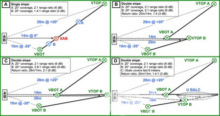
Figure 3: Up/down split example. In all of the examples, a listening area covering 20 degrees above the vertical axis of the loudspeaker and 20 degrees below the axial direction of the loudspeaker is required. (A) A single speaker array can cover a continuous bevel. (B) It is not necessary to divide the speaker array when the return coefficient is 3 dB. (C) When the return coefficient is 6 dB, the speaker needs to be divided into upper/lower parts. (D) Use the pick-up speaker to reduce the return factor to 3dB (no need to split the speaker array).
Secondary options for up/down split main speaker system
In addition to splitting the speaker array, we have other options. We can divide the coverage area. For example, the area below the stage can be covered with a delay speaker group, so that the area covered by the delay speaker group can be removed from the area coverage requirement of the main speaker system. This system design reduces the distance between the VTOP2 and the speaker set, while also reducing the turndown ratio and the opening angle of the bevel. A single main speaker system can even be used if the delay speaker set is able to raise the return factor above the lower limit.
The height of the main speaker system is also an important factor. In the previous section, we have already seen the situation when the main speaker system is in the vertical plane centerline. Increasing the mounting height of the main speaker system can reduce the angular difference between VBOT1 and VTOP2 (in fact, this angle difference is already small enough). However, increasing the mounting height of the main speaker system brings about a problem of partitioning in the lower area (a line of sight between the listening area and the main speaker system), which results in a reduction in the coverage area and a reduction in the return factor.
In this case, the setting of the delay speaker group changes from an option to a mandatory option. This visual obstruction has a serious negative impact on the coverage of the area under the stage, so the setting of the delay speaker group cannot be considered as an effective means of obtaining the return coefficient gain. Lowering the mounting height of the main speaker system below the pick-up line ensures visibility of the main speaker system in the area below the pick, but also increases the spread angle of the slope of the listening area.
At this point, the return factor has not improved, and the coverage of the stage has become more challenging. From the perspective of the main speaker system, the sound pressure level slope curve at the upper end is flat. However, due to the reduction in coverage angle and the increase in the turndown ratio, a large coverage beam correction must be performed on the upper end of the main speaker system. It is very difficult to achieve such a large degree of asymmetry for a single beveled listening area coverage. For a single main speaker system, it is a demanding requirement to cover both the base and the base under these conditions, especially when the position of the pick is relatively high.
There is also a highly relevant consideration: the cover characteristic that is described as "smile and frown" is curved.
This phenomenon is related to the orientation of the upper/lower end of the front of the table (the area we wish to avoid).
Only the main speaker system located in the axis of the vertical plane enables precise beam steering to avoid high return coefficients.
Higher or lower mounting heights produce variations in coverage characteristics at different heights in the room.
Consolation is that if we no longer insist on using a single speaker array but split the speaker array into upper/lower parts, then the above problems will not occur.
Instead of trying to accomplish an impossible task with a speaker array (covering a double-layered beveled listening area), it is better to use two speaker arrays: to achieve an asymmetric coupling point source to cover a single beveled listening area. And the little price we have to pay is that the frequency response will increase in the low frequency part.
This system design is basically two separate system designs. The power of the upper and lower speaker arrays is equal, but requires independent analysis and calculation.
In some cases, the upper main speaker system mounting position can be moved toward the listening area (because the coverage area of ​​this group of speakers is the beginning of the pick). This installation method can reduce the power required by the system and improve the signal-to-noise ratio without affecting the sound image.
Picking the front
There is an old saying on the front of the stage that can be a good expression of the sound system engineer's view: the only good front is that there is no front. "Picking phobia" is a serious illness in the audio industry. What audio system designers have racked their brains to avoid is exactly what acoustic designers are trying to achieve: “active†fronts. As audio system engineers, we have all been troubled by the stage, so it is necessary to use a few words to describe this from the right perspective. Some of the picks are harmful to the audio system and some are harmless, but usually we will face both of them at the same time.
Harmful picks are high front, "active" and non-characteristic (single angle, no diffuse reflection), or materials are glass and stainless steel (harmful). For audio system speakers, their angles are also bad, reflecting the sound to the stage or the audience. The more serious (worst case) is the plane or curved pick in a fan-shaped field with a stage because they produce acoustic focus.
A good pick should be a small front size, "inactive", diffuse reflection, full of various fixtures, multiple angles and tilting. This kind of stage will reflect the sound to audio such as ceiling. System harmless area. We can measure the front of the stage to assess how much it affects the audio system, such as a front height of no more than 0.5m. The frequency band below 500Hz is harmless. The key point is not to affect the system design by avoiding factors that do not adversely affect the audio system (see Figure 4).
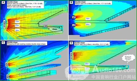
Figure 4: Up/Down Split is an example of a main speaker system design. (A) The use of a fill speaker under the stage reduces the return factor, so a single main speaker system can be used. (BD) uses a split-type up/down main speaker system design.
Speaker
Wireless Speaker Custom Accept,Bluetooth Speakers Outdoor,Bluetooth Kids Speaker,Mini Kids Speaker
Shenzhen Ruidian Technology CO., Ltd , https://www.wisonen.com