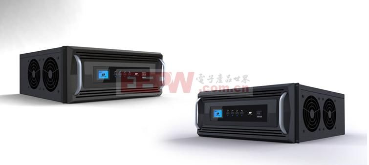
In our daily lives, we often use 220V AC power and convert it to DC using a rectifier. The inverter, on the other hand, performs the opposite function—converting DC power back into AC. That’s why it's called an inverter. But how exactly does it work? What is its core principle? Let's dive into the details below.
First, the Principle of the Inverter – Introduction
An inverter, also known as a converter or inverter, works by transforming direct current (DC) into alternating current (AC), typically converting it into 220V AC for household use. It can be categorized into different types, such as half-bridge and full-bridge inverters. Today, inverters are widely used in various devices like computers, TVs, air conditioners, refrigerators, and fans.

Second, the Inverter Schematic
The inverter consists of several key components, including the inverter bridge, control logic, and filter circuit. A typical schematic includes the input interface, voltage start loop, MOS switch tube, DC conversion loop, PWM controller, feedback loop, LC oscillation and output loop, and load. Each part plays a crucial role in ensuring stable and efficient operation.

Third, the Inverter Principle
Let’s take a closer look at how each component contributes to the inverter’s operation:
- Input Interface: This section receives three signals: 12V DC voltage (VIN), working enable voltage (ENB), and panel current control (DIM). VIN is usually provided by an adapter, while ENB comes from the microcontroller (MCU) and determines whether the inverter is active. DIM controls the current supplied to the load.
- Voltage Start Circuit: This circuit activates the backlight when ENB is set to 3V, indicating that the inverter is operating normally.
- PWM Controller: This component manages the DIM signal and provides protection against overvoltage, undervoltage, and short circuits. It also handles pulse width modulation for precise control.
- DC Conversion Loop: Composed of a MOSFET switch and an inductor, this loop converts the DC input into AC by charging and discharging the inductor cyclically.
- LC Oscillation and Output Circuit: This part ensures the correct voltage is delivered during startup and stabilizes it once the system is running.
- Feedback Loop: Used to maintain stable voltage output during normal operation.
Overall, the inverter operates by first converting DC into AC through an oscillating circuit, then boosting the voltage using a coil to generate a square wave, and finally shaping it into a sine wave through rectification.

Fourth, the Inverter Principle – Application
One of the most common applications of inverters is in cars. Car inverters allow you to power electronic devices while on the go. They offer several advantages:
- They break the limitations of using electrical appliances in vehicles, making it easy to connect devices directly through the inverter.
- Using a car inverter is straightforward: simply plug it into the cigarette lighter socket, turn it on, and insert your device into the outlet.
- Car inverters are designed with safety in mind. They automatically shut down in case of overload or short circuits.
- These inverters are not only suitable for vehicle systems but can also work with any 12V DC power source.

Understanding the inverter principle helps us appreciate the technology behind modern electronics. Whether it's powering your phone in the car or supporting home appliances, inverters play a vital role in our daily lives.
Battery Charger,ebike battery charger,ebike charger,water purifier charger
FOSHAN SHUNDE KELICHENG POWER SUPPLY TECHNOLOGY CO., LTD , https://www.kelicpower.com