A. Circuit working principle
This article refers to the address: http://
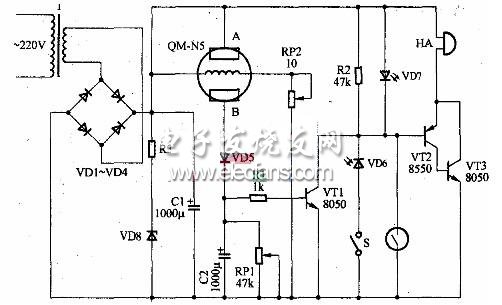
The multi-function alarm is composed of a power supply circuit and a harmful gas detection circuit. Anti-theft alarm device, dawn "small alarm clock" device and sound and light alarm device, as shown.
The power circuit is composed of a power transformer T, rectifier diodes VD1 to VD4, a smoothing capacitor C1, and a Zener diode VD8.
The harmful gas detection circuit is composed of a gas sensor QM-N5, an adjustable resistor RP1, a RP2, a diode VD5 and the like.
The anti-theft alarm device is mainly composed of a reed switch and a small magnet.
The dawn "small alarm clock" device is mainly composed of a switch S and a photodiode VD6.
The sound and light alarm device is mainly composed of a colorful light emitting diode VD7 and a piezoelectric buzzer HA.
1. The process of harmful gas alarm circuit
In normal times, the gas sensor QM-N5 does not come into contact with harmful gases (carbon monoxide, gas, liquefied petroleum gas, etc.), and the resistance between the two poles A and B is large. At this time, the diode VD5 is not turned on, so that the transistors VT1, VT2, VT3 Both are off, the sound and light alarm device does not work. When the concentration of harmful gases in the monitored area reaches a certain value, the resistance between the two electrodes of the gas sensors A and B will become smaller, and the diode VD5 will be turned on. At this time, the devices E2 and R1 will be delayed for a period of time (the delay is short) Mainly to prevent false alarms. After the delay is over, the triodes VT1, VT2 and VT3 are saturated and turned on, so that the piezoelectric buzzer HA emits an alarm sound, and the colorful light-emitting diode VD7 emits colorful light, realizing the requirement of harmful gas alarm.
Additional application of this circuit diagram: small alarm clock and burglar alarm
1. Daylight "small alarm clock" circuit working process
During the day, the switch S is disconnected and can be closed at night. After the S is closed at night, the photodiode VD6 can't receive the light. At this time, the VD6 is not turned on, so that the triodes VT2 and VT3 are all turned off; the sound and light alarm device does not work. When the day is bright or the light reaches a certain requirement. The photodiode VD6 senses the signal so that its internal resistance becomes small and conducts, so that the triode VT2 and VT3 are saturated and turned on, and the sound and light alarm device sounds and emits light to realize the purpose of the "small alarm clock".
2. Anti-theft alarm circuit working process
The reed switch can only work with a small magnet, that is, the reed switch contact is disconnected when the small magnet is close to the reed switch, and vice versa. Usually the reed switch and the small magnet are together, that is, the reed switch contact is disconnected (when there is no thief), the triode VT2, VT3 are cut off, and the sound and light alarm device does not work. When the thief moves the small magnet hidden by the reed switch, the reed switch contacts are closed, so that the triode VT2 and VT3 are saturated and conducting, and the sound and light alarm device sounds and emits light to realize the purpose of anti-theft alarm.
Yuan Zhen selection
The gas sensor adopts QM-N5 type gas sensor; VT1 and VT3 select S8050 silicon NPN transistor, VT2 selects S8550 silicon PNP transistor; RP1, RP2 selects self-locking organic solid potentiometer; VD1~VD5 selects lN4007 rectifier Diode; C1, C2 select the electrolytic capacitor R1 ~ R3 with the withstand voltage value of 15V to select 1/4W carbon film resistor or metal film resistor; piezoelectric buzzer HA select HY-3015A, voltage: 3V ~ 24V; VD6 select General photodiode; VD7 uses a colorful LED. T selects 220/6V, 5W power transformer.
Production and debugging
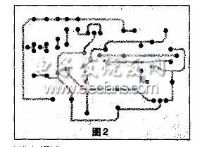
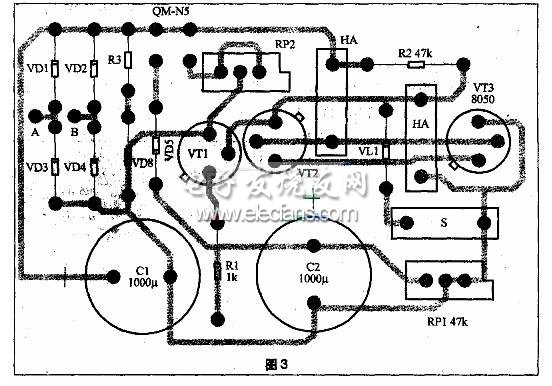
This paper provides a printed circuit board diagram of the entire alarm circuit. As shown in Figure 2, according to the printed circuit board diagram, the circuit board can be fabricated first. After the circuit board is manufactured, the circuit is mounted and soldered according to the alarm circuit assembly drawing as required. The board is shown in Figure 3. In the assembly diagram, the two terminals A and B are connected to the secondary of the transformer T, and the colorful light-emitting diode VD7 can be connected to both ends of the piezoelectric buzzer HA.
Because the operating voltage of the heating wire of the gas sensor QM-N5 is 5V, when the circuit board is soldered, the potentiometer RP2 should be adjusted so that the voltage across the heating wire of the gas sensor is 5V. Adjust the resistance of the potentiometer RP1 to adjust the sensitivity of the harmful gas alarm circuit. When debugging, first turn on the power, after preheating for 10 minutes, align the air sensor with the air outlet of the lighter, and gently press the lighter (the lighter is out, but do not let the lighter fire), and slowly adjust the resistance of the potentiometer RP1. So that the piezoelectric buzzer HA just sounds an alarm. Stop the air supply and press the buzzer HA to stop the alarm. After a few minutes, use the same gas to supply air and check if the alarm can quickly alarm. Repeat several times to increase the sensitivity of the alarm so that it can work reliably. After the debugging is completed, tighten the tightening nut on the potentiometer RP shaft handle.
With full capacity of 1810mAh,this IPhone 6 Battery perfectly matches the iphone 6 mobile,it's particular chip and battery cell technology makes this Iphone Battery higher quality than our competitors,stable performance and unique functional board date input lasting the battery life span with over 500 cycle times.We have strict test process from material,half end to end products,more than 5 times are inspected thorough of many aspects such as technical date,battery cell,appearance,function,capacity and etc.We have CE,RoHS and FCC certificates to make sure our mobile phone batteriesall are approved by international standard.A good reputation has been awarded from our worldwide customers,await for your cooperation!
As a professional manufacturer over 7 years experience, Hequanqingnuo technology owns the brand of HQQNUO involved in different kinds of Cell Phone Battery such as IPhone Battery , Huawei Battery , Samsung Battery and other Cell Phone Accessories, such as IPhone Battery Case, QI Car Charger ,Wireless Phone Charger etc.
OEM/ODM and more forms of customization are supported by us.

Iphone 6 Battery
Iphone 6 Battery,Apple 6 Battery,Iphone 6 External Battery,Apple Iphone 6 Battery
Shenzhen Hequanqingnuo Electronic Technology Co., Ltd. , https://www.hqqnbattery.com