PLC control content and working principle
2 .1 Constant power excitation control
Constant power excitation control mainly refers to the control of the excitation of the exciter in the main generator, specifically: when the locomotive is in traction mode, the constant power control of the diesel engine is achieved at different diesel engine speeds. The PLC obtains the given power at the current diesel engine speed according to the actually detected diesel engine speed and the pre-saved diesel engine power-speed curve; then calculates the actual power value based on the collected main circuit voltage and traction motor current (6 motors) , The deviation of the two, and the deviation of the voltage value and the voltage limit value, the current value and the current limit value, take the minimum value for PID adjustment calculation, and adjust the excitation current of the main generator through the chopper, so that the output of the main generator The power is adjusted towards the power given value to realize the constant power control of the main generator. The control block diagram is shown in Figure 1. During the control process, PLC monitors the voltage and current of the traction motor to achieve functions such as constant power, voltage limiting, current limiting, and single motor fault removal.
2.2 Control of auxiliary systems
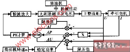
Figure 1 Block diagram of the power control system The control of the auxiliary system includes the control of the diesel engine, the control of the air compressor, the control of sand and air source purification devices, etc. PLC realizes effective control of each component of the auxiliary system according to the working logic of each component.
2.3 Magnetic field weakening control
The PLC automatically performs two-stage magnetic field weakening control according to the change of locomotive speed. In order to reduce the current strike during the transition, the PLC has the function of first reducing the power and then transitioning.
2.4 Anti-idling control When the locomotive is towing, the PLC obtains the maximum current difference and current distribution coefficient from the detected output currents of the six main generators. When the current distribution coefficient is greater than the specified value and the current of the smallest motor is greater than the specified value, it is regarded as idling, and the PLC will eliminate it by sanding and continuously reducing the main generator output voltage. After the idling phenomenon disappears, the output voltage of the main generator can return to the normal value, and the sanding will stop after a delay of about 3 seconds. If the idling cannot be eliminated, the locomotive is unloaded (during the same loading process, it is allowed to occur twice).
2.5 Fault protection
Based on the detected main generator voltage, the current of each traction motor, diesel engine speed, oil pressure and cooling water temperature, the PLC compares it with the specified limit parameters. When a certain parameter is exceeded, the PLC will take an alarm, unload or stop And other measures to protect the locomotive diesel engine and electrical system.
2.6 Stepless speed regulation of diesel engine
PLC realizes the same function as WJT. The PLC controls the operation of the stepper motor by detecting the position of the driver's main handle (up, up, down).
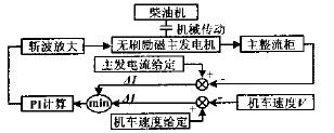
Figure 2 Block diagram of constant low speed control system
PID adjustment calculation, and the excitation current of the exciter in the main generator is adjusted by chopping, so that the locomotive speed is adjusted to the speed given value, and the low constant speed control of the locomotive is realized. The control block diagram is shown in Figure 2.
Table Gas Cooker,Gas Stoves,Gas Cookers,Tabletop Stoves
Xunda Science & Technology Group Co.ltd , https://www.xundatec.com