Keywords: MCU, sensor, dual-tone multi-frequency, wireless data transmission, program monitoring. With the continuous improvement of material life, people are more concerned about the safety of personal and property, looking forward to the birth of an intelligent alarm system that can act as a watchdog . The wireless intelligent alarm system introduced in this article can promptly detect the imminent emergency (theft, fire, etc.) in the monitoring place and quickly dial the alarm call, so that effective measures can be taken in time to minimize the damage and loss to life and property. This system mainly adopts the technology of single chip microcomputer program control, wireless data transmission, dual tone multi-frequency signal generation, E2PROM reading and writing, telephone off-hook, infrared sensor, vibration sensor, smoke sensor and serial asynchronous communication between single chip computers. Because of the wireless transmission method, the system has good concealment and strong survivability. More importantly, it avoids the disadvantages of installing and disassembling the wired alarm system, which is troublesome to install and disassemble, and destroys the existing reasonable structure. Application prospects.
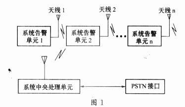
1 The overall structure of the system The wireless intelligent alarm system consists of the system alarm unit, the system central processing unit and the public telephone network interface. The block diagram is shown in Figure 1. When a system alarm unit detects an abnormality, it sends a signal through the antenna; this signal is processed by the central processing unit of the system, and finally alarmed by telephone notification.
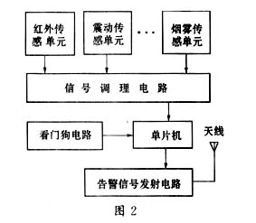
2 System hardware composition and characteristics The system hardware includes two parts: system alarm unit hardware and system central processing unit hardware. The system alarm unit hardware is mainly composed of AT89C2051 single-chip microcomputer, alarm acquisition circuit, alarm transmission circuit and watchdog circuit. The block diagram is shown in Figure 2.
The hardware of alarm central processing unit is mainly composed of AT89C51 microcontroller, alarm receiving circuit, telephone off-hook circuit, dialing circuit, number writing and reading circuit, number display circuit and watchdog circuit. The block diagram is shown in Figure 3.
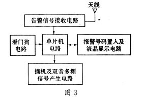
The user can use the keys of the home phone to put the alarm number (which can be the user's office phone number, mobile phone number, public 110 alarm phone number or any other number) into the E2PROM through the number placement circuit. The placement process can be See through the LCD display. The alarm signal is received by the antenna of the central processing unit and enters the receiving circuit. The receiving circuit sends a dial-up start signal to the single-chip computer. The single-chip computer reads the pre-set alarm number through the number reading circuit, and then enters the circuit through off-hook and dual-tone multi-frequency signal generation circuit Telecommunications network, users can take corresponding measures when they know it.
2. The one-chip computer of the one-chip computer system warning unit adopts 89C2051 of ATMEL Company, built-in 128 bytes of RAM, 2K bytes of FLASH, 15 I / O ports, there are 20 pins outside. The single chip microcomputer of the central processing unit of the system adopts ATMEL's 89C51, built-in 256 bytes of RAM, 4K bytes of FLASH (flash memory), 2 16-bit counters / timers, 32 I / O ports and 5 interrupt sources , A full-duplex serial port, an accurate analog comparator, on-chip oscillator and clock circuit. There are 40 pins on the outside, and the package is DIP (dual in-line). Others are the same as 89C2051. 2.2 The watchdog circuit has various interference sources at the working site of the single chip microcomputer. These interference sources are likely to cause the program to run away, causing crashes or abnormal operation of the program. If it is not restored in time, it is easy to cause losses. The watchdog is a special circuit that resets or resets the system to make the system run normally when the program runs or crashes. The watchdog circuit here takes MAX813L as the core and adds several resistors and capacitors. MAX813L is a low-cost microprocessing monitoring chip developed by MAXIM. It has 8 pins on the outside and is packaged in the form of DIP. The main functions are the RESET output and manual reset input terminal under power-on, power-off, and step-down.
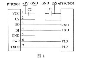
2.3 The core component of the wireless transmitter and receiver circuit The wireless transmitter and receiver circuit uses PTR2000, which is an ultra-small, ultra-low-power high-speed wireless data transmission MODEM launched by Harbin Xuntong Electronic Technology Co., Ltd. It can be directly connected to the serial port of the single-chip microcomputer, and Manchester coding is not required, and the application and programming are very convenient. The specific application circuit is shown in Figure 4 (only the PTR2000 is used in the alarm board, and its use in the central board is almost the same as this).

In Figure 5, the role of the varistor R is to adjust the brightness of the LCD screen under backlight. In practical applications, it is best to connect a switch in series with the varistor so that the backlight function is activated only when needed. It should be noted that the dual audio signal comes out of the telephone when the keyboard is dialed, and it can be received by the single-chip microcomputer after conversion, and this process is completed by MT8880 in the dial circuit.
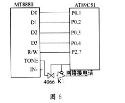
2.5 Dial-up circuit The dial-up circuit is mainly composed of a dual-tone multi-frequency chip MT8880, a multi-way switch 4066, a relay, an NPN type triode, and a small number of resistors and capacitors. The function of MT8880 is to convert the digital signal written by the single-chip microcomputer into a dual audio signal, and send the alarm number to the public telephone network when the control dial-out relay is turned on and the phone is off-hook. Conversely, it can also convert the dual audio signals from the keyboard into digital signals and send them to the microcontroller. The specific circuit is shown in Figure 6.
It was found in the experiment that the ability to dial depends on whether the phone is off-hook reliably. If the phone is not off-hook, other hardware and software are useless even if they are completely correct. To this end, we must pay attention to choose a good performance relay. The purpose of using 4066 is to ensure that number setting and dialing are isolated from each other and do not affect each other.
3 System software design The system software includes system alarm unit software and system center

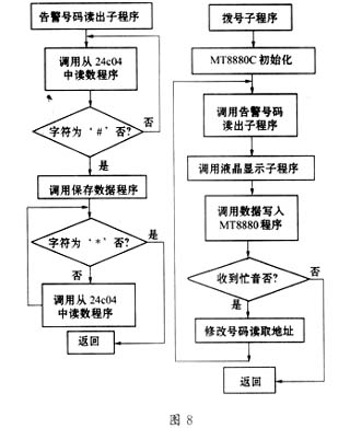
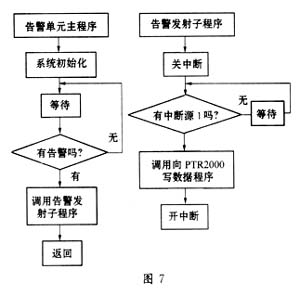
The main program of the alarm unit is in the interrupt working mode. After the system initialization is completed, it starts to wait for the interrupt response to be generated. If the sensor detects the induction source, the program is executed downwards, and a coded pulse train with a specific meaning is sent out wirelessly. The main program of the central processing unit is in the query mode. After the system is initialized, it starts to detect the receiving buffer cyclically. If data is received, the program will execute the start dialing alarm downward; if no data is received, wait. Here, the asynchronous serial working mode is adopted between the alarm unit and the central processing unit. Add several alarm numbers in advance to quickly dial other numbers when the dialed line is busy. It should also be pointed out that due to the limited response speed of the public telephone network, there must be sufficient time delay between off-hook and dialing, and between dialing two adjacent numbers.
2 Chen Longsan. 8051 MCU C language control and application. Beijing: Tsinghua University Press, 2000
3 Zhang Zhirong, etc. Research and development of intelligent flow measurement system. Electronic Technology Application, 2001 (2)
N95 Mask
Three-layer structure high-density filter
Name: 3-layer non-woven (adult size)
Packaging: 50 pcs
Size: about 175 * 95mm
Carton Size: 52*40*32cm
N.W.: 6.8kg
Suitable for respiratory protection, filtering dust, haze, bacteria, droplets and other harmful particles in the air.

WIDELY USE –Outdoor cycling, home decoration, all the filter efficiency indicators are above 99%, effective dust prevention, PM2.5 industry, irritant gas, haze, particulate matter, allergy, pollen, automobile exhaust, etc.
FAQ:
Advantages:
1. WE ARE FACTORY! We have our ownshare factory in shenzhen, Very welcome to visit if available.
2. OEM & ODM
3. Short delivery time
4. Environmentally-friendly material
5. Good workmanship
6. We always ship by international express, air and sea.
7. We serve with best quality and service.
N95 Mask
Shenzhen Dianjiang Engineering Co. LTD , https://www.isourceled.com