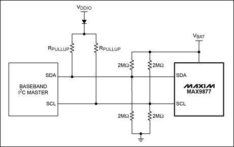
Method 1—Add weak pull-up The first method is to add additional weak pull-up resistors on SDA and SCL when the conventional pull-up resistor is invalid to establish the voltage on the bus. Figure 1 shows this Schematic diagram of the method.

Figure 1. The weak pull-up resistor divider is used to set the voltage of the SDA data line and SCL clock line; the isolation diode prevents current loss when the pull-up voltage is forced to ground
A pair of 2MΩ resistors on the SDA and SCL lines divide the battery voltage so that the voltage on the SDA and SCL lines does not exceed the maximum withstand voltage of the I²C host. The battery voltage range is 4.2V to 3.2V, so the voltage on the SDA and SCL lines is set between 2.1V and 1.6V, which is sufficient to support the MAX9877 input high voltage.
When the output of VDDIO is forcibly connected to ground, the diode can be drained by the disabled VDDIO power supply. If the power supply is disabled and has a high-impedance output, the diode can be omitted.
This method also assumes that the output of the I²C host and all other devices on the bus are in a high-impedance state during shutdown. One reason may make this assumption untenable: if the power supply of the I²C host is powered down, the output is clamped to 0V by the integrated ESD protection. This situation is not common, but if it occurs, you must use method 2 or method 3 to raise SDA and SCL.
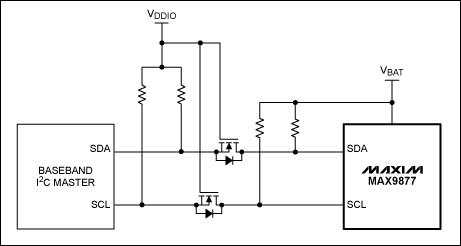
Method 2-Level shifter If other devices on the bus cannot be surely placed in a high-impedance state when the system interface is turned off, a single n-channel enhancement mode MOSFET can be used to isolate each bus from the rest of the system. An additional pull-up resistor can be added on the MAX9877 side of the bus to set the logic level to high.
Figure 2 shows the circuit to implement this scheme. VDDIO is the system I²C pull-up voltage, and all four resistors must be selected based on the system I²C timing requirements. The n-channel MOSFET is used as a bidirectional level shifter, allowing the logic levels of the MAX9877 and baseband to be different, without affecting normal operation. When the VDDIO power supply is disabled, the level shifter allows the MAX9877's SDA and SCL pins to remain high, thus reducing the shutdown current. .

Figure 2. Add n-channel MOSFET level shifter to isolate system bus
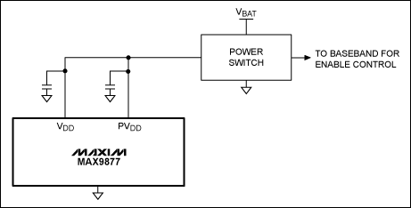
Method 3—High-side power switch The last method to reduce the MAX9877's shutdown current is to connect a high-side switch in series with the MAX9877 power supply. If necessary, the power supply can be completely disconnected from the battery and reduce the MAX9877's shutdown current to less than 1µA.
Figure 3 shows the connection between the high-side switch and the MAX9877. The MAX9877 has two power supply pins (VDD and PVDD), and the voltage difference between the two must be kept within 0.3V. Use a power switch to keep the two power supplies at the same voltage and reduce the number of components.

Figure 3. The high-side power switch is connected in series with the MAX9877 power supply to completely eliminate the shutdown current
Ceramic Fan Heaters is a Fan-forced space heaters have a fan behind the PTC heating element to push warmed air outward, so they heat the room quicker than radiant heat models. Ceramic heater make a bit more noise than radiant heat styles, which are typically silent, But we call it White Noise. As you might imagine, the main component of a Fan Heater is the fan motor, which moves air pass a PTC heating element and then into the room or office. The most common source of heat for fan heaters is electricity. Portable models are plugged into a power outlet, which provides the heat to warm the air being passed through the PTC heater.
Ceramic Fan Heater inclduing portable PTC heater, Wall mounted PTC heater, Ceramic tower heater.
if you want to get more info, pleae contact us
thanks
Ceramic Fan Heater
Dimplex Ceramic Tower Heater,Arlec Ceramic Heater,Comfort Zone Oscillating Heater,Ceramic Tower Fan Heater
Fenry manufacturing Co., Ltd , https://www.cnfenry.com