Summary
This article refers to the address: http://
NFC Near Field Communication is a short-range, high-frequency wireless communication technology that allows non-contact point-to-point data transmission (within ten centimeters) to exchange data between electronic devices. This technology evolved from radio frequency identification (RFID) technology and is backward compatible with RFID. By using NFC technology in smart TV applications, it is easy to quickly pair and share content with devices such as smartphones and TV sets. Easily paired with an NFC-enabled remote control and NFC TV, the mirror mode can be activated in seconds and begin streaming content to a large screen or home theater. In fact, NFC technology is also used in Bluetooth pairing, mobile payment, direct information interaction and preservation applications.
1 NFC smart TV system structure and overall design
This design uses TI's TRF7970A transceiver IC as the TV terminal, RF430CL330H NFCTag is applied to the remote control terminal; in this system, its basic functions are as follows:
· The TRF7970A can communicate with the RF430CL330H to enable pairing between the TV and the remote control, which is the current pairing before 2.4GHz data transmission;
· The TRF7970A enables fast pairing of WiFi with NFC smartphones;
· RF430CL330H can communicate with the smartphone to convert the data information of the mobile phone to the remote control or TV;
· Software upgrades to Firmware via NFC's air interface;
· TRF7970A can read and write the label to realize the function selection of the TV;
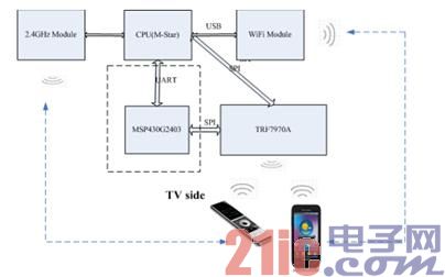
Figure 1 System block diagram
The TRF7970A meets NFC's three functional communication methods: Reader/Write, Pear to Pear and Card Emulaiton, which fully meet the ISO/IEC18092, ISO/IEC21481 NFC standards; can fully interact with the NFC-compliant device side, RF430CL330H is A dynamic NFC Tag chip that meets NFC Type 4 standards and supports data rates up to 848Kbps. The SPI interface enables efficient communication with the MCU.
2 hardware circuit design
2.1 TRF7970A module hardware circuit design
The TRF7970A is a 13.56MHz RFID highly integrated RF front-end chip that fully supports the NFC protocol standard. By configuring the chip's ISO Control register, it can be set to work in different modes. The TRF7970A supports both SPI and parallel port communication. Interface mode, wide voltage (2.7V~5.5V) power supply, integrated LDO, support 5 power management modes, output power up to 200mW with 5V power supply. There are two channels in the receiving loop (RX1 and RX2), and the phase difference is 90 degrees to ensure the stability and reliability of the receiving. The basic hardware circuit is shown in the figure below:
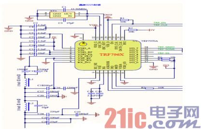
Figure 2 TRF7970A RF front-end circuit
The RF front end is matched to a 50 ohm RF impedance. The basic matching network is as follows:
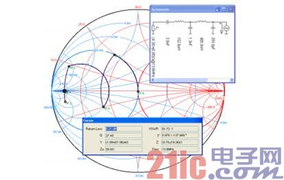
Figure 3 TRF7970A RF front-end matching network
2.2 TRF7970A antenna matching circuit construction
The TRF7970A antenna is a 50 ohm impedance matching antenna. The basic matching circuit is as follows:
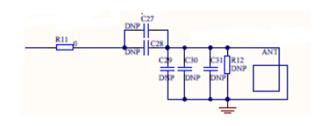
Figure 4 TRF7970A antenna matching circuit
Due to the different materials and sizes of the antennas, each of the TRF7970A antenna matching circuit antennas produced must have complete antenna matching. According to the designed system Q value and the inductance value of the antenna, the parameters of the RF front end are completely matched. .
2.3 RF430CL330H module hardware circuit design
The RF430CL330H is a dynamic tag that satisfies NFC Type 4, supports ISO/IEC14443 Type B, supports SPI and I2C interfaces, and has a dynamic tag with RF wake-up function. The basic hardware circuit is as follows:
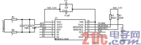
Figure 5 RF430CL330H basic reference circuit
As can be seen from the schematic, few external components can be integrated into other peripheral circuits to achieve fast NFC functionality. In this remote control project, the RF430CL330H and peripheral circuits are integrated into the circuit of the remote control, but the coil is taken out as a separate module, which is convenient for reading and writing operations.
3 system software design
The system software design mainly includes the realization of various functions in the smart TV application: there is a right to read the TAG to obtain a specific TV or network program, and there is a need for Bluetooth pairing WIFI pairing to quickly establish a connection between Bluetooth and WIFI, and The TV can obtain mobile phone related pictures and link information through P2P function, and realize fast switching of information. Wireless firmware can also be upgraded via NFC.
3.1 Tag reading
The TRF7970A supports reading of ISO15693, ISO14443A/B and other tags (as shown in Figure 6).
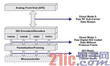
Figure 6 Card Standards Supported by TRF7970A
3.2 Bluetooth pairing
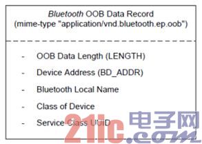
According to the Bluetooth Secure Simple paring using NFC (NFCForum-AD-BTSSP) specification defined by the NFC Forum and the Bluetooth SIG Alliance, the Bluetooth pairing information (such as the following array) is written to the NDEF area of ​​the RF430CL330H through the MCU, when any NFC-enabled device After the content is read, the Bluetooth pairing connection process will be automatically performed.
The OOB data format of Bluetooth is shown in Figure 7. Includes OOB data length, Bluetooth device address and name, device type, and UUID.
The NDEF write information data structure of Bluetooth is as follows:
Unsigned char NDEF_Application_Data[] =
{
//NDEF Tag Application Name
0xD2, 0x76, 0x00, 0x00, 0x85, 0x01, 0x01,
//Capability Container ID
0xE1, 0x03,
//Capability Container
0x00, 0x0F, //CCLEN
0x20, //Mapping version 2.0
0x00, 0x3B, //MLe (49 bytes); Maximum R-APDU data size
0x00, 0x34, //MLc (52 bytes); Maximum C-APDU data size
0x04, //Tag, File Control TLV (4 = NDEF file)
0x06, //Length, File Control TLV (6 = 6 bytes of data for this tag)
0xE1, 0x04, //File Identifier
0x0C, 0x02, //Max NDEF size (3072 bytes)
0x00, //NDEF file read access condition, read access without any security
0x00, //NDEF file write access condition; write access without any security
//NDEF File ID
0xE1, 0x04,
0x00, 0x44, //NLEN; NDEF length (68 byte long message)
0xD2, //MB=1b, ME=1b, CF=0b, SR=1b, IL=0b, TNF=010b
0x20, //Record Type Length: 32 octets
0x21, //payload length: 33 octets;
0x61, 0x70, 0x70, 0x6C, 0x69, 0x63, 0x61, 0x74, 0x69, 0x6F, 0x6E, 0x2F, 0x76,
0x6E, 0x64, 0x2E, 0x62, 0x6C, 0x75, 0x65, 0x74, 0x6F, 0x6F, 0x74, 0x68, 0x2E,
0x65, 0x70, 0x2E, 0x6F, 0x6F, 0x62, //Record Type Name: application/vnd.blue
//tooth.ep.oob
0x21, 0x00, //OOB optional data length: 33 octets
0x06, 0x05, 0x04, 0x03, 0x02, 0x01, //bluetooth device address:
//01:02:03:04:05:06 (example address only)
0x0D, //EIR Data Length: 13 octets
0x09, //EIR Data Type: Complete Local Name
0x48, 0x65, 0x61, 0x64, 0x53, 0x65, 0x74, 0x20, 0x4E, 0x61, 0x6D, 0x65, //
//Bluetooth Local Name: HeadSet Name
0x04, //EIR Data Length: 4 octets
0x0D, //EIR Data Type: Class of device
0x04, 0x04, 0x20, //Class of Device: 0x20:Service Class=
//Audio, 0x04: Major Device Class=Audio/Video, 0x04: Minor Device Class=Wearable //Headset Device
0x05, //EIR Data Length: 5 octets
0x03, //EIR Data type: 16-bit Service Class UUID list (complete)
0x1E, 0x11, 0x0B, 0x11 //16-bit Service Class UUID list (complete) ;0x111E –
//HFP-HF, 0x011B ?A2DP-SNK
};
3.3 Peer to Peer
P2P is based on the Simple NDEF Exchange Protocol (NFCForum-TS-SNEP) specification defined by the NFC Forum. The main process is as follows. The mobile phone can quickly exchange related information such as pictures, links, etc. with the TV through the function of P2P.
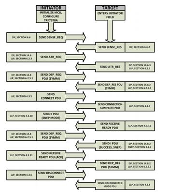
Figure 8 P2P software operation process
In P2P, devices are divided into active mode Initiator and passive mode Target. The TRF7970A can be used both as an Initiator and as a Target. Relatively speaking, Target mode can effectively save power.
1. Active mode: The device itself generates RF electromagnetic fields
2. Passive mode: The device uses the induced electromagnetic field for data transmission
![]()
Figure 9 P2P working mode
3.4 Firmware Update
Combine the BSL function of the MCU with the technology of NFC, and implement software upgrade through P2P. Taking TI's MSP430 as an example, BSL's software mainly includes Peripheral Interface (PI), Command Interface and BSL_API. BSL's software upgrade interface can be through UART, SPI, then NFC interface and SPI can be combined to achieve software upgrade through NFC. As shown in Figure 10.
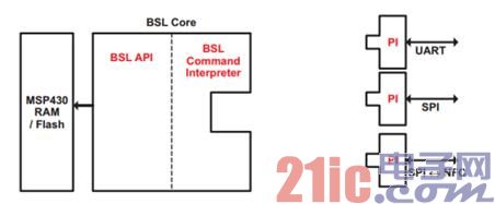
Figure 10 BSL software upgrade method
Among them, NFC's PI mainly includes three layers: SPI driver, RFID hardware interface (interface with TRF7970A) and NFC (NFC protocol implementation, P2P) function.
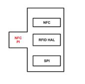
Figure 11 NFC PI structure
4 Summary
With the continuous popularization of NFC near field communication functions, it has a wide range of applications in different fields due to its fast transmission rate and high security. Especially in the authorization, payment, Bluetooth and WIFI pairing has a prominent advantage, the introduction of NFC applications into smart TV, making information sharing, communication connections more convenient and fast, will greatly enhance the user experience.
Commercial electric LED emergency double heads light is perfect for applications requiring a dependable, long lasting, energy efficient life safety solution with a traditional design. The twin heads emergency light is designed with injection-molded, flame-retardant, high impact thermoplastic housing .The adjustable heads allow for optimal lighting of the path of egress.

Emergency Exit Lights,2 Head Emergency Light,Twin Spot Emergency Light,Led Twin Spot Emergency Lights
Jiangmen City Pengjiang District Qihui Lighting Electrical Appliances Co., Ltd , https://www.qihuilights.com